
Network Virtualization using Extreme Fabric Connect
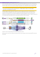

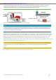

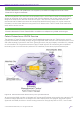


Table Of Contents
- Table of Contents
- Table of Contents
- Table of Contents
- Table of Figures
- Table of Figures
- Table of Tables
- Conventions
- Introduction
- Reference Architecture
- Guiding Principles
- Architecture Components
- User to Network Interface
- Network to Network Interface
- Backbone Core Bridge
- Backbone Edge Bridge
- Customer MAC Address
- Backbone MAC Address
- SMLT-Virtual-BMAC
- IS-IS Area
- IS-IS System ID
- IS-IS Overload Function
- SPB Bridge ID
- SPBM Nick-name
- Dynamic Nick-name Assignment
- Customer VLAN
- Backbone VLAN
- Virtual Services Networks
- I-SID
- Inter-VSN Routing
- Fabric Area Network
- Fabric Attach / Auto-Attach
- FA Server
- FA Client
- FA Proxy
- FA Standalone Proxy
- VPN Routing and Forwarding Instance
- Global Router Table
- Distributed Virtual Routing
- Zero Touch Fabric (ZTF)
- Foundations for the Service Enabled Fabric
- IP Routing and L3 Services over Fabric Connect
- L2 Services Over SPB IS-IS Core
- Fabric Attach
- IP Multicast Enabled VSNs
- Extending the Fabric Across the WAN
- Distributed Virtual Routing
- Quality of Service
- Consolidated Design Overview
- High Availability
- Fabric and VSN Security
- Fabric as Best Foundation for SDN
- Glossary
- Reference Documentation
- Revisions

Network Virtualization Using Extreme Fabric Connect
© 2019 Extreme Networks, Inc. All rights reserved. 101
source VLAN and another L2 segment (VLAN) for the VSN users attached to the FA Proxy access switch
performing MVR. Note that this implies that the VSN that owns the IP multicast source is an L3 VSN (or IP
Shortcut instance) which can thus have multiple L2 segments on the VRF/GRT that terminates the VSN.
Caution
The Extreme Networks MVR implementation on ERS platforms does not allow IGMP
receivers on the MVR source VLAN.
Another related use case, depicted in Figure 50, would be a deployment where it is desired that all
virtualized VSNs be allowed to receive IPTV channels as a shared fabric service. In this case a simpler
approach is to place the IPTV source into a dedicated IP multicast enabled L2 VSN. There will be no
receivers or end-stations within the IPTV L2 VSN (so a single L2 segments is all that is needed). Instead, the
L2 VSN itself becomes the MVR source VLAN across all access FA Proxy switches.
Figure 50 Inter-VSN IP Multicast with Fabric-wide MVR L2 VSN
Now any user in any VSN or VSN type across the fabric can be made to receive the shared IPTV multicast
application.