
Network Virtualization using Extreme Fabric Connect
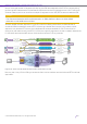


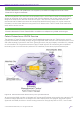
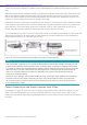


Table Of Contents
- Table of Contents
- Table of Contents
- Table of Contents
- Table of Figures
- Table of Figures
- Table of Tables
- Conventions
- Introduction
- Reference Architecture
- Guiding Principles
- Architecture Components
- User to Network Interface
- Network to Network Interface
- Backbone Core Bridge
- Backbone Edge Bridge
- Customer MAC Address
- Backbone MAC Address
- SMLT-Virtual-BMAC
- IS-IS Area
- IS-IS System ID
- IS-IS Overload Function
- SPB Bridge ID
- SPBM Nick-name
- Dynamic Nick-name Assignment
- Customer VLAN
- Backbone VLAN
- Virtual Services Networks
- I-SID
- Inter-VSN Routing
- Fabric Area Network
- Fabric Attach / Auto-Attach
- FA Server
- FA Client
- FA Proxy
- FA Standalone Proxy
- VPN Routing and Forwarding Instance
- Global Router Table
- Distributed Virtual Routing
- Zero Touch Fabric (ZTF)
- Foundations for the Service Enabled Fabric
- IP Routing and L3 Services over Fabric Connect
- L2 Services Over SPB IS-IS Core
- Fabric Attach
- IP Multicast Enabled VSNs
- Extending the Fabric Across the WAN
- Distributed Virtual Routing
- Quality of Service
- Consolidated Design Overview
- High Availability
- Fabric and VSN Security
- Fabric as Best Foundation for SDN
- Glossary
- Reference Documentation
- Revisions

Network Virtualization Using Extreme Fabric Connect
© 2019 Extreme Networks, Inc. All rights reserved. 110
and use this VRF to allocate the Fabric Extend IP interfaces used to send and receive traffic from the
Internet. This VRF will never be L3 VSN enabled.
Note
Use of the GRT (VRF-0) or an L3 VSN enabled VRF for terminating Fabric Extend tunnels
should be avoided when deploying Fabric Extend over the Internet. The Fabric Connect
VPN interface used for Fabric Extend will most likely need to be located in the enterprise
DMZ and only the Fabric Extend IP will be allowed out of the Firewall. Fabric Internet
access should be performed using alternative GRT or L3VSN services which will have a
separate connectivity via the enterprise Firewall.
Figure 57 Fabric Extend Deployment Model over Public Internet with IPSec
Fabric Extend over E-LAN/VPLS Service
The diagram in Figure 58 shows a typical Fabric Extend deployment over an L2 any-to-any WAN service
which is typically delivered by the WAN provider using MPLS VPLS. In the example shown, a hub-and-
spoke topology was used for the Fabric Extend IP tunnels, but could equally have been fully meshed or a
combination. All IP tunnels terminate on Fabric Extend logical IS-IS interfaces that are capable of
terminating one or more IP tunnels (and thus IS-IS interfaces) on the same physical Ethernet port.
The WAN provider is offering an L2 service and it is up to the customer to allocate a single IP subnet to use
across the geographical L2 segment so that the Fabric Extend IP tunnels can be created as required.