
Network Virtualization using Extreme Fabric Connect
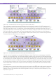
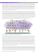


Table Of Contents
- Table of Contents
- Table of Contents
- Table of Contents
- Table of Figures
- Table of Figures
- Table of Tables
- Conventions
- Introduction
- Reference Architecture
- Guiding Principles
- Architecture Components
- User to Network Interface
- Network to Network Interface
- Backbone Core Bridge
- Backbone Edge Bridge
- Customer MAC Address
- Backbone MAC Address
- SMLT-Virtual-BMAC
- IS-IS Area
- IS-IS System ID
- IS-IS Overload Function
- SPB Bridge ID
- SPBM Nick-name
- Dynamic Nick-name Assignment
- Customer VLAN
- Backbone VLAN
- Virtual Services Networks
- I-SID
- Inter-VSN Routing
- Fabric Area Network
- Fabric Attach / Auto-Attach
- FA Server
- FA Client
- FA Proxy
- FA Standalone Proxy
- VPN Routing and Forwarding Instance
- Global Router Table
- Distributed Virtual Routing
- Zero Touch Fabric (ZTF)
- Foundations for the Service Enabled Fabric
- IP Routing and L3 Services over Fabric Connect
- L2 Services Over SPB IS-IS Core
- Fabric Attach
- IP Multicast Enabled VSNs
- Extending the Fabric Across the WAN
- Distributed Virtual Routing
- Quality of Service
- Consolidated Design Overview
- High Availability
- Fabric and VSN Security
- Fabric as Best Foundation for SDN
- Glossary
- Reference Documentation
- Revisions

Network Virtualization Using Extreme Fabric Connect
© 2019 Extreme Networks, Inc. All rights reserved. 121
Note
The DVR Backbone I-SID uses reserved value 16678216.
The DVR domain I-SID uses reserved range 16678216 + DVR domain ID; hence the DVR
domain ID 1 I-SID will take value 16678217, domain ID 2, 16678218 and so on.
Also, if DVR leaf nodes are SMLT enabled, I-SID range 16677215 + Cluster ID is used for the
vIST connection.
Tip
There is no need to configure the DVR domain & Backbone I-SIDs. These are automatically
inferred once the node has been configured as a DVR controller or leaf for a given DVR
domain.
Once the DVR controllers and DVR leaf nodes are in place, it becomes possible to create DVR-enabled
segments. From a configuration perspective, these are created much in the same way as an L2 VSN is
created and to which a local IP interface is assigned. The IP interfaces can belong to one of many VRFs
which in turn may belong to fabric-wide L3 VSN tenants. The configuration needs to be consistent across
the DVR controllers in the sense that all DVR controllers within the same DVR domain should have the same
DVR segments.
On these segments, each DVR controller will have its own local and unique IP interface as well as virtual
DVR Gateway IP which needs to be the same IP address across all DVR controllers. This is conceptually
similar to how VRRP is configured. It is this DVR Gateway IP address that will need to be used as Default
Gateway IP by all server/VM hosts residing on the DVR segment.
Note
If a DVR segment is only configured on one of the DVR controllers, it will be immediately
active across all the DVR leaf nodes and will be operational. However, for resiliency and
load balancing purposes, that DVR segment needs to be provisioned across all DVR
controllers in the DVR domain.
DVR segments will typically also get created across multiple DVR domains, as shown in Figure 66, based on
the data center requirements for how far a server VLAN/segment needs to stretch. As such the DVR
segment will need creating across all DVR controllers for all the DVR domains where it is required. The
same DVR Gateway IP will need to be configured on all DVR controllers.
As soon as a DVR segment has been configured on a DVR controller, the DVR controller immediately
advertises the existence of the segment via the Domain DVR I-SID with a single point-to-multipoint update
to reach all DVR leaf nodes within the DVR domain. These use IS-IS based LSP updates which are reliably
acknowledged and contain information about the DVR segment including:
• L2 I-SID
• L3 I-SID (0 if IP Shortcuts)
• DVR Gateway IP
• IP Mask
• IP routes
• IP Multicast state and IGMP version to use
The information exchanged via the DVR domain I-SID will be stored by all DVR nodes within the DVR
domain in a separate LSDB from the SPB’s regular IS-IS LSDB so that the latter does not get overloaded.
The DVR leaf nodes will use this information to activate the distributed anycast gateway in their data plane,
which will then allow them to handle ARP/RARP/GARP directly with the server/VM hosts and to perform