
Network Virtualization using Extreme Fabric Connect
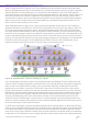

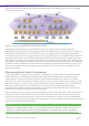
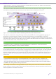


Table Of Contents
- Table of Contents
- Table of Contents
- Table of Contents
- Table of Figures
- Table of Figures
- Table of Tables
- Conventions
- Introduction
- Reference Architecture
- Guiding Principles
- Architecture Components
- User to Network Interface
- Network to Network Interface
- Backbone Core Bridge
- Backbone Edge Bridge
- Customer MAC Address
- Backbone MAC Address
- SMLT-Virtual-BMAC
- IS-IS Area
- IS-IS System ID
- IS-IS Overload Function
- SPB Bridge ID
- SPBM Nick-name
- Dynamic Nick-name Assignment
- Customer VLAN
- Backbone VLAN
- Virtual Services Networks
- I-SID
- Inter-VSN Routing
- Fabric Area Network
- Fabric Attach / Auto-Attach
- FA Server
- FA Client
- FA Proxy
- FA Standalone Proxy
- VPN Routing and Forwarding Instance
- Global Router Table
- Distributed Virtual Routing
- Zero Touch Fabric (ZTF)
- Foundations for the Service Enabled Fabric
- IP Routing and L3 Services over Fabric Connect
- L2 Services Over SPB IS-IS Core
- Fabric Attach
- IP Multicast Enabled VSNs
- Extending the Fabric Across the WAN
- Distributed Virtual Routing
- Quality of Service
- Consolidated Design Overview
- High Availability
- Fabric and VSN Security
- Fabric as Best Foundation for SDN
- Glossary
- Reference Documentation
- Revisions

Network Virtualization Using Extreme Fabric Connect
© 2019 Extreme Networks, Inc. All rights reserved. 122
first-hop IP routing for any L3 flow received from those hosts. In case IP Multicast for the segment was
enabled on the DVR controller, the DVR leaf nodes will also automatically activate IGMP on the same
segment using the requested IGMP version. When the DVR leaf activates a new DVR interface for the DVR
segment, it will allocate a local VLAN-ID and VRF-ID out of its local pool.
Tip
Each DVR leaf has a local pool of 4000 VLAN-IDs and 255 VRFs which are no longer user
configurable but instead get allocated sequentially to the DVR interfaces created on the
DVR controllers.
Caution
Currently a DVR leaf will support a maximum of 500 DVR interfaces and hence will at
most consume 500 VLAN-IDs from the available pool.
Note
Extreme Networks VSP 7200 and 8k platforms by default support a maximum of 24 VRFs.
In order to scale to 255 VRFs it is necessary to activate the vrf-scaling boot flag, which in
turn will reduce the VLAN-ID pool to 3500. The vrf-scaling boot flag, if set, should be
enabled across all DVR leaf and controller nodes.
By default, the DVR controllers will also push to the DVR leaf nodes a default route to themselves, which
will result in every DVR leaf also installing a default route towards the DVR controllers. IP ECMP will always
be enabled on the DVR leaf nodes and if more than one DVR controller is present in the DVR domain, and
with SPB equal shortest path, then these default routes will leverage IP ECMP to distribute traffic needing
to leave the DVR domain across the available DVR controllers.
In DVR designs where multiple exit points are desired from a given DVR domain, the DVR controllers placed
at those exit points can be configured to not advertise a default route and/or instead advertise a more
specific IP route leveraging DVR redistribution.
It should be noted that not all server segments operating in a DVR domain need be DVR enabled segments.
It is perfectly acceptable to have some segments created with VRRP on the DVR controllers and for these
segments to be simply terminated on DVR leaf nodes using Switched-UNI end-points. In this case, these
segments will not be handled by DVR signaling and will operate in the traditional way, meaning that the
DVR leaf will only be able to perform L2 switching for these segments and any IP routing will need to be
performed on the DVR controllers. This flexibility is important to ensure that data center DVR architectures
can be made to work even for applications that are currently not supported by DVR.
Note
Currently DVR segments can only be created for IPv4. The DVR architecture is already
defined also for IPv6 operation but IPv6 support will become available in a future software
release. Should IPv6 be required in a server segment, the segment will need to be
provisioned using traditional VRRP v3 for both IPv4 and IPv6.