
Network Virtualization using Extreme Fabric Connect


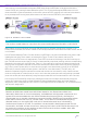
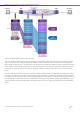
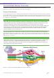
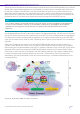
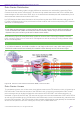
Table Of Contents
- Table of Contents
- Table of Contents
- Table of Contents
- Table of Figures
- Table of Figures
- Table of Tables
- Conventions
- Introduction
- Reference Architecture
- Guiding Principles
- Architecture Components
- User to Network Interface
- Network to Network Interface
- Backbone Core Bridge
- Backbone Edge Bridge
- Customer MAC Address
- Backbone MAC Address
- SMLT-Virtual-BMAC
- IS-IS Area
- IS-IS System ID
- IS-IS Overload Function
- SPB Bridge ID
- SPBM Nick-name
- Dynamic Nick-name Assignment
- Customer VLAN
- Backbone VLAN
- Virtual Services Networks
- I-SID
- Inter-VSN Routing
- Fabric Area Network
- Fabric Attach / Auto-Attach
- FA Server
- FA Client
- FA Proxy
- FA Standalone Proxy
- VPN Routing and Forwarding Instance
- Global Router Table
- Distributed Virtual Routing
- Zero Touch Fabric (ZTF)
- Foundations for the Service Enabled Fabric
- IP Routing and L3 Services over Fabric Connect
- L2 Services Over SPB IS-IS Core
- Fabric Attach
- IP Multicast Enabled VSNs
- Extending the Fabric Across the WAN
- Distributed Virtual Routing
- Quality of Service
- Consolidated Design Overview
- High Availability
- Fabric and VSN Security
- Fabric as Best Foundation for SDN
- Glossary
- Reference Documentation
- Revisions

Network Virtualization Using Extreme Fabric Connect
© 2019 Extreme Networks, Inc. All rights reserved. 140
Data Center Distribution
The data center distribution model is slightly different as here there is a real benefit in extending Fabric
Connect all the way to the ToR switches. This allows to high speed interconnect the ToRs in smaller data
center designs as well as the use of DVR, which in all cases ensures shortest path and lowest latency for all
data center east-west and north-south traffic flows.
In a DVR design the data center distribution will be performing the role of DVR controllers and as such all
L3 VSNs for the data center will be provisioned on these nodes as well as the corresponding VRF instances
and server L2 VSN segments.
Tip
If the data center topology is spine-leaf, then either the spines become DVR controllers or
a pair of border leaf nodes are made the DVR controllers. Either way, the DVR controllers
represent the point of entry and exit for data center traffic.
As illustrated in Figure 83, these Distribution nodes can thus use inter-VSN routing capability whereby
traffic can be IP routed on or off a server L2 VSN segment as well as providing IP routing between these
server L2 VSN segments.
Tip
In a DVR architecture, the DVR controller is not likely to do much inter-VSN routing as the
DVR leaf nodes would have already IP routed the flow directly at the ToR access layer.
Figure 83 Zoom on Data Center Distribution BEB / DVR Controller
Data Center Access
To complete the picture, we will also zoom into the data center access ToR switches, which will be acting as
DVR leaf nodes. These switches are part of the SPB fabric and will typically be deployed as SMLT cluster
pairs so that servers can be dual-homed with active-active LACP LAG SMLT links where necessary. As
illustrated in Figure 84, the DVR leaf ToR switches will have much the same awareness of VRFs and L3VSNs
as well as all the available server L2 VSNs within the DVR domain since this is automatically pushed to them
from the DVR controllers. The ToR switches will also present a distributed anycast gateway for the attached
servers and will perform the first IP routing hop for any non-L2 data center flow.