
Network Virtualization using Extreme Fabric Connect


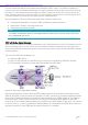
Table Of Contents
- Table of Contents
- Table of Contents
- Table of Contents
- Table of Figures
- Table of Figures
- Table of Tables
- Conventions
- Introduction
- Reference Architecture
- Guiding Principles
- Architecture Components
- User to Network Interface
- Network to Network Interface
- Backbone Core Bridge
- Backbone Edge Bridge
- Customer MAC Address
- Backbone MAC Address
- SMLT-Virtual-BMAC
- IS-IS Area
- IS-IS System ID
- IS-IS Overload Function
- SPB Bridge ID
- SPBM Nick-name
- Dynamic Nick-name Assignment
- Customer VLAN
- Backbone VLAN
- Virtual Services Networks
- I-SID
- Inter-VSN Routing
- Fabric Area Network
- Fabric Attach / Auto-Attach
- FA Server
- FA Client
- FA Proxy
- FA Standalone Proxy
- VPN Routing and Forwarding Instance
- Global Router Table
- Distributed Virtual Routing
- Zero Touch Fabric (ZTF)
- Foundations for the Service Enabled Fabric
- IP Routing and L3 Services over Fabric Connect
- L2 Services Over SPB IS-IS Core
- Fabric Attach
- IP Multicast Enabled VSNs
- Extending the Fabric Across the WAN
- Distributed Virtual Routing
- Quality of Service
- Consolidated Design Overview
- High Availability
- Fabric and VSN Security
- Fabric as Best Foundation for SDN
- Glossary
- Reference Documentation
- Revisions

Network Virtualization Using Extreme Fabric Connect
© 2019 Extreme Networks, Inc. All rights reserved. 148
Tip
On earlier platforms using the original IST implementation (before vIST), the IST DMLT
would be provisioned to also act as an SPB NNI MLT interface.
Taking advantage of the SPB Fabric, the above IST restrictions have been removed with the introduction of
Virtual IST (vIST) on the latest Extreme Networks VSP series platforms. With a vIST, the IST is no longer tied
to any physical MLT instance, but is instead associated with an L2VSN I-SID. Hence, provided that both IST
peers are still connected to the same SPB Fabric, IS-IS will always be able to compute a shortest path
connection for the IST connection to use. Each SMLT cluster switch now will mostly just need redundant
NNI connections into the SPB Fabric.
Tip
With vIST, there is no requirement for the SMLT cluster switches to share a direct NNI
connection (as shown in Figure 86). In most cases, however, it will still make sense to have
a direct SPB NNI connection between the two switches, but this connection will be no
different from any other SPB NNI interface and there is no longer any need for it to be of
DMLT type.
Tip
Also, with vIST the SMLT cluster pair do not have to be the same switch model (though it
usually makes sense for them to have the same number of interfaces).
A further enhancement of SMLT when operating with SPB is that the SMLT cluster operates with an SMLT-
Virtual-BMAC which ensures that any traffic ingressing the SPB Fabric via the SMLT cluster nodes will be
Mac-in-Mac encapsulated with a source BMAC, which is not the node’s individual BMAC, but instead the
SMLT cluster’s SMLT-Virtual-BMAC. This ensures that on the distant egress BEBs, where the same traffic
egresses the SPB Fabric, reverse CMAC learning will learn the source CMACs as reachable via the SMLT
cluster SMLT-Virtual-BMAC and return traffic can then be load-balanced back toward both SMLT cluster
nodes leveraging whatever BVLAN allocation is used across all the distant BEBs.
Note
The SMLT-Virtual-BMAC can be manually provisioned or auto-generated.
Thus, SMLT clustering not only provides active-active load balancing of traffic ingressing
the Fabric Connect, but also provides multi-path load balancing within the SPB Fabric for
traffic egressing the Fabric Connect on the SMLT cluster.
Active/Active IP Gateway Redundancy with SMLT
As stated in the previous section, the SMLT IST performs synchronization of L2 related tables to make both
switches in the SMLT cluster appear as one switch. However, from an L3 IP perspective, both switches
remain independent IP routers, each with their own IP addresses.
Note
An MLAG implementation where both nodes share the same IP interfaces is to be avoided
as it requires an Active/Standby control plane (where the software on one switch controls
both switches in the MLAG cluster) with all the disadvantages that entail in case of node
failure. For example, loss of interconnecting communication channel between MLAG peers
becomes catastrophic and results in duplicate IP conditions.