
Network Virtualization using Extreme Fabric Connect

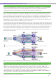


Table Of Contents
- Table of Contents
- Table of Contents
- Table of Contents
- Table of Figures
- Table of Figures
- Table of Tables
- Conventions
- Introduction
- Reference Architecture
- Guiding Principles
- Architecture Components
- User to Network Interface
- Network to Network Interface
- Backbone Core Bridge
- Backbone Edge Bridge
- Customer MAC Address
- Backbone MAC Address
- SMLT-Virtual-BMAC
- IS-IS Area
- IS-IS System ID
- IS-IS Overload Function
- SPB Bridge ID
- SPBM Nick-name
- Dynamic Nick-name Assignment
- Customer VLAN
- Backbone VLAN
- Virtual Services Networks
- I-SID
- Inter-VSN Routing
- Fabric Area Network
- Fabric Attach / Auto-Attach
- FA Server
- FA Client
- FA Proxy
- FA Standalone Proxy
- VPN Routing and Forwarding Instance
- Global Router Table
- Distributed Virtual Routing
- Zero Touch Fabric (ZTF)
- Foundations for the Service Enabled Fabric
- IP Routing and L3 Services over Fabric Connect
- L2 Services Over SPB IS-IS Core
- Fabric Attach
- IP Multicast Enabled VSNs
- Extending the Fabric Across the WAN
- Distributed Virtual Routing
- Quality of Service
- Consolidated Design Overview
- High Availability
- Fabric and VSN Security
- Fabric as Best Foundation for SDN
- Glossary
- Reference Documentation
- Revisions

Network Virtualization Using Extreme Fabric Connect
© 2019 Extreme Networks, Inc. All rights reserved. 155
Tip
From a CFM standpoint, performing L2 ping or traceroute or tracetree on the ingress BEB
needs to be performed on the corresponding BVLAN. This remains deterministic as
required by SPB, whereby BEB-1 uses BVLAN1 while BEB-2 uses BVLAN2.
We’ll conclude this section by looking at how IP Multicast load balancing is handled with Fabric Connect. As
already mentioned in IP Multicast Over SPB on page 89, each and every multicast stream (defined by a
unique combination of Group IP address, Source IP address and ingress BEB) is allocated an I-SID that
defines the shortest path multicast tree to deliver that stream to any BEB that has signalled its interest in
being part of it (based on whether or not it has IGMP receivers). These I-SID trees can be created
independently in one or the other BVLAN. Let us consider the example in Figure 91, where again the four
paths between BEB-1 (or BEB-2) and BEB-3 are all of equal cost.
Source-Group streams 1 & 2 originate from BEB-3. Stream 1 was the first stream detected by BEB-3, hence
it was dynamically assigned I-SID 16000001 on BVLAN1. Stream 2 was detected next, and was assigned to
I-SID 16000002 on BVLAN2. And so on. Essentially, the Multicast reserved I-SIDs 16000001-16600000 are
still assigned to BVLAN1 and BVLAN2 on an even/odd basis. However, they are assigned sequentially, as
new IP Multicast streams are detected by the ingress BEB. This therefore produces a good spread of
multicast streams across both BVLANs and we can see that spread translating into an effective load
balancing for Streams 1 & 2.
Figure 91 IP Multicast Load Balancing into SPB Equal Cost Shortest Path Trees
Tip
BEB-1 will always forward stream 1 onto the SMLT links towards the receiver, because
BEB-1 is primarily operating on BVLAN1 within the SMLT cluster. Likewise, BEB-2 for
stream 2 on BVLAN2. However, BEB-2 will also add itself to the multicast tree of stream 1
on BVLAN1 (and likewise BEB-1 for stream 2 on BVLAN2), because it might have to
forward stream 1 on its SMLT link, should the SMLT link of BEB-1, or BEB-1 itself, suddenly
fail. The solution consistently delivers sub-second failover.