
Network Virtualization using Extreme Fabric Connect


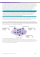
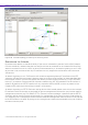
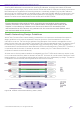
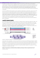
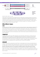

Table Of Contents
- Table of Contents
- Table of Contents
- Table of Contents
- Table of Figures
- Table of Figures
- Table of Tables
- Conventions
- Introduction
- Reference Architecture
- Guiding Principles
- Architecture Components
- User to Network Interface
- Network to Network Interface
- Backbone Core Bridge
- Backbone Edge Bridge
- Customer MAC Address
- Backbone MAC Address
- SMLT-Virtual-BMAC
- IS-IS Area
- IS-IS System ID
- IS-IS Overload Function
- SPB Bridge ID
- SPBM Nick-name
- Dynamic Nick-name Assignment
- Customer VLAN
- Backbone VLAN
- Virtual Services Networks
- I-SID
- Inter-VSN Routing
- Fabric Area Network
- Fabric Attach / Auto-Attach
- FA Server
- FA Client
- FA Proxy
- FA Standalone Proxy
- VPN Routing and Forwarding Instance
- Global Router Table
- Distributed Virtual Routing
- Zero Touch Fabric (ZTF)
- Foundations for the Service Enabled Fabric
- IP Routing and L3 Services over Fabric Connect
- L2 Services Over SPB IS-IS Core
- Fabric Attach
- IP Multicast Enabled VSNs
- Extending the Fabric Across the WAN
- Distributed Virtual Routing
- Quality of Service
- Consolidated Design Overview
- High Availability
- Fabric and VSN Security
- Fabric as Best Foundation for SDN
- Glossary
- Reference Documentation
- Revisions

Network Virtualization Using Extreme Fabric Connect
© 2019 Extreme Networks, Inc. All rights reserved. 168
By default, all innate IP services are based on the GRT. This is the only viable channel of management
communication without the use of dedicated VSNs and physical loopback of management interfaces, which
quickly results in an obtuse implementation. By removing the client user and device communities from the
GRT we provide for a very clean and dedicated IP environment for the management of the fabric and
security infrastructure. No security demarcation interfaces should be allowed between the GRT and the
user community domains. (If any are allowed, proper security exception procedures should be followed and
maintained.)
Access to the GRT should be based on strong multifactor authentication as required by the environmental
security policies of the organization. Ideally, the administrator should possess two separate devices for
access. One device would be dedicated for access to the GRT with associated separate user credentials for
administrative concerns and another for normal user access with separate user credentials for normal
access. While virtualization can be used to achieve same device separation, it is outside of the scope of any
separation that the fabric provides and therefore is a potential point of exposure to the GRT. Best security
practices for the given virtualization environment should be followed. Given that we have made
accommodations for the isolation of the GRT we will now address the various user level services that the
fabric has available.
Layer 2 Virtual Service Networks
As covered earlier, L2 VSNs are nothing more than VLANs at the service edge associated with I-SIDs in the
service core. Note that at the very basic primitive the L2 VSN is a true Layer 2 phenomenon. It can exist
completely on its own without the use of any IP whatsoever. Moreovver, these services can be extended
farther and more extensively than any traditional tagged VLAN approach. By default, they have no
association to any VRF. As such they result in totally isolated L2 domains of interest that are totally ‘dark’
because there is simply no IP against the context of the topology.
Figure 97 DHCP Services for L2 Virtual Service Networks
As the figure above illustrates, you can even run DHCP services within the L2VSN and provide for a default
gateway for a complete IP user environment but the only point of exposure is the default gateway. There is
no other way in or out for the service. There is an obvious ‘data corralling’ effect that occurs in this scenario
and it allows for a security demarcation for the service and any allowed external traffic. This is a great
approach for controlled access environments such as captive portals for guests or contractors or in highly
regulated environments such as PCI.
Note however that if any VLAN termination assigned to the given I-SID were provisioned with an IP
address, it would appear in the GRT and have access to the network control plane as shown in the
illustration below.