Extreme Campus Controller Deployment Guide Version 5.46.
Copyright © 2021 Extreme Networks, Inc. All rights reserved. Legal Notice Extreme Networks, Inc. reserves the right to make changes in specifications and other information contained in this document and its website without prior notice. The reader should in all cases consult representatives of Extreme Networks to determine whether any such changes have been made. The hardware, firmware, software or any specifications described or referred to in this document are subject to change without notice.
Table of Contents Preface......................................................................................................................................................................................vii Conventions.................................................................................................................................................................. vii Text Conventions...........................................................................................................
Table of Contents Editing Device Group Profile for Network and Role.................................................................................59 Creating Adoption Rules........................................................................................................................................62 Centralized Site with AAA Network................................................................................65 Deployment Strategy..............................................................
Table of Contents Default Access Control Rules......................................................................................................................118 Define Rule Precedence......................................................................................................................................... 119 Deploying Centralized Web Authentication................................................................ 120 Deployment Strategy..................................................
Table of Contents Editing the Device Group Profile for ECP Network.................................................................................195 PHP External Captive Portal, Controller’s Firewall Friendly API.............................. 197 net-auth.php............................................................................................................................................................... 197 login.php............................................................................
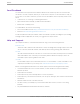
Preface Read the following topics to learn about: • • • The meanings of text formats used in this document. Where you can find additional information and help. How to reach us with questions and comments. Conventions To help you better understand the information presented in this guide, the following topics describe the formatting conventions used for notes, text, and other elements.
Preface Documentation and Training Table 2: Text Convention Description screen displays This typeface indicates command syntax, or represents information as it is displayed on the screen. The words enter and type When you see the word enter in this guide, you must type something, and then press the Return or Enter key. Do not press the Return or Enter key when an instruction simply says type. Key names Key names are written in boldface, for example Ctrl or Esc.
Send Feedback Preface Send Feedback The Information Development team at Extreme Networks has made every effort to ensure that this document is accurate, complete, and easy to use. We strive to improve our documentation to help you in your work, so we want to hear from you. We welcome all feedback, but we especially want to know about: • • • Content errors, or confusing or conflicting information. Improvements that would help you find relevant information. Broken links or usability issues.
Subscribe to Product Announcements Preface Subscribe to Product Announcements You can subscribe to email notifications for product and software release announcements, Field Notices, and Vulnerability Notices. 1. 2. 3. 4. 5. Go to The Hub. In the list of categories, expand the Product Announcements list. Select a product for which you would like to receive notifications. Select Subscribe. To select additional products, return to the Product Announcements list and repeat steps 3 and 4.
About Extreme Campus Controller Deployment Deploying Extreme Campus Controller on page 11 VE6120K, VE6125K Virtual Appliances on page 11 VE6120H Virtual Appliance on page 12 VE6120 Virtual Appliance on page 12 VE6125 Virtual Appliance on page 13 Supported Appliance Specifications on page 14 Discovery and Registration on page 16 Sites on page 21 Device Groups on page 22 Deploying Extreme Campus Controller The Deployment Guide will guide you through the process of deploying your access points using Extreme C
About Extreme Campus Controller Deployment VE6120H Virtual Appliance • Accepts the same capacity keys as other models Note VE6120K and VE6125K use separate image files. You cannot upgrade from one VM model to another. Virtual Machine Upgrade File Formats: • • VE6120K — .dve VE6125K — .mfe Requirements for the Extreme Campus Controller VE6120K and VE6125K models are listed in Supported Appliance Specifications on page 14.
About Extreme Campus Controller Deployment VE6125 Virtual Appliance Virtual Machine Upgrade File Formats: Note VE6120, and VE6125 use separate .ova files. You cannot upgrade from one VM model to another. Virtual Machine Upgrade File Formats: • • VE6120 — .dle VE6125 — .rse Requirements for the Extreme Campus Controller VE6120 model are listed in Supported Appliance Specifications on page 14.
Supported Appliance Specifications About Extreme Campus Controller Deployment Supported Appliance Specifications Extreme Campus Controller supports the following virtual appliances: • VMWare: ◦ VE6120 ◦ VE6125 • KVM ◦ VE6120K ◦ VE6125K • Microsoft Hyper-V ◦ VE6120H And the following hardware appliances: • • • • E1120 E2120 E2122 E3120 Requirements for each Extreme Campus Controller model are listed below.
About Extreme Campus Controller Deployment Supported Appliance Specifications Table 4: Virtual Extreme Campus Controller (VE6120 and VE6125) (continued) Extreme Application VE6120 VE6125 RAM (GB) 8 16 24 32 Hard Disk (GB) 80 80 80 512 • Consult VMWare ESXi for minimum host performance requirements for virtual environment. Performance depends on network interface characteristics of underlying host and on utilization on shared interfaces by other virtual appliances.
About Extreme Campus Controller Deployment Discovery and Registration Table 6: Virtual Extreme Campus Controller (VE6120K and VE6125K) (continued) Extreme Application VE6120K VE6125K Total Switches managed per Appliance 50/100 100/200 200/400 200/400 Total simultaneous users in Standalone mode 1,000 4,000 8,000 16000 Additional simultaneous users in highavailability mode 1,000 4,000 8,000 16000 Total Simultaneous Users per Appliance Pair 2,000 8,000 16,000 32000 CPU 4 6 8 20 Cor
About Extreme Campus Controller Deployment Discovery Process for APs and Adapters in a Centralized Site Discovery Process for APs and Adapters in a Centralized Site Note The following process outlines device discovery and registration for AP39xx, AP4xx, and AP5xx access points, and SA201 adapters, in a Centralized site. Extreme Campus Controller supports Extreme Defender Adapter SA201 for the Defender for IoT solution.
Discovery Process for APs and Adapters in a Centralized Site About Extreme Campus Controller Deployment Figure 2: Discovery Process for devices in a Centralized site Discovering Centralized Site APs and Adapters Once an AP has successfully registered with a controller, it recalls that controller's IP address, and uses that address on subsequent reboots. The AP bypasses discovery and goes straight to registration. Use the IP address of the controller to which the AP last connected successfully.
About Extreme Campus Controller Deployment Switch Discovery Process If a known controller cannot be located, take the following steps: 1. Use DHCP Option 60 to query the DHCP server for available controllers. The DHCP server responds to the AP with Option 43, which lists the available controllers. For the DHCP server to respond to an Option 60 request from an AP, configure the DHCP server with the vendor class identifier (VCI) for each AP model.
About Extreme Campus Controller Deployment Switch Discovery Process • • On-premises Extreme Management Center or ExtremeCloud IQ - Site Engine ExtremeCloud™ IQ Note Only one appliance at a time can be configured as the Management Appliance. When the switch is turned on, it automatically starts the Linux process cloud-connector client. The cloud-connector client relies on the Default VLAN 1 enabled DHCP client to discover a DHCP server.
About Extreme Campus Controller Deployment Sites Once Extreme Campus Controller acknowledges the switch configuration, the switch enters the machine state Running. This state is represented in Extreme Campus Controller with a green circle.
About Extreme Campus Controller Deployment Device Groups • • • • • • • • • • • • • • • • AP4000 AP410i/e AP410i-1 AP410C AP460i/e AP460C/S6C/S12C AP505i AP510i/e AP510i-1 AP560i/h AP3917i/e/k AP3916ic AP3915i/e AP3912i AP3935i/e AP3965i/e A Defender site is a Centralized site that supports SA201. It begins with the DFNDR_ prefix. The licensing domain is defined at the site level. When configuring a site, select the Country value that matches the licensing domain of the APs that comprise the site.
Configuring DHCP, NPS, and DNS Services DHCP Service Configuration on page 23 Configuring the Extreme Campus Controller as an NPS Client on page 42 NPS Service Configuration on page 43 DNS Service Configuration on page 48 Configure Extreme Campus Controller for Local DHCP Management on page 51 This chapter describes how to configure DHCP and DNS (Domain Name System) services on a Windows Server 2012 R2 or Linux server for use by ExtremeWireless Appliance and APs.
Configuring DHCP on Windows Server 2012 R2 Configuring DHCP, NPS, and DNS Services DHCP options provide specific configuration and service information to DHCP clients. The options described here are specific to pointing an AP to its adopter and setting the correct MINT link level. The option value you configure is specific to your network site type. When you configure DHCP for Extreme Campus Controller, include 078 SLP DA Option for access points on a Centralized site.
Configuring DHCP, NPS, and DNS Services Configuring DHCP on Windows Server 2012 R2 5. Select Next. The IP Address Range window is displayed. Figure 4: IP Address Range 6. In the Start IP address and the End IP address text boxes, type the start and end of the IP address range that you want to be distributed to the network. You must use the range provided by your network administrator. 7.
Configuring DHCP on Windows Server 2012 R2 Configuring DHCP, NPS, and DNS Services 11. In the Days, Hours and Minutes text box, type the lease duration. You must use the Lease Duration as specified by your network administrator. 12. Select Next. The Configure DHCP Options window displays. 13. Select Yes, I want to configure these options now, and then select Next. The Router (Default Gateway) window displays. 14. In the IP address text box, type the network’s default gateway and select Add.
Configuring DHCP, NPS, and DNS Services Configuring DHCP on Windows Server 2012 R2 15. Select Next. The Domain Name and DNS Servers window displays. Figure 6: Domain Name and DNS Servers 16. In the Parent domain text box, type your company’s domain name. You must use the Parent Domain provided by your network administrator. 17. In the Server name text box, type your server name. You must use the server name provided by your network administrator. 18.
Configuring DHCP on Windows Server 2012 R2 Configuring DHCP, NPS, and DNS Services Create New DHCP Options When you configure DHCP for Extreme Campus Controller, create 078 SLP DA Option for access points on a Centralized site. Note You can create the DHCP options at the scope level or at the server IPv4 node. When you configure DHCP options at the server node, the options apply to all scopes under that node.
Configuring DHCP, NPS, and DNS Services Configuring DHCP on Windows Server 2012 R2 78 Description Optional description. For example, Extreme Networks SLP Discovery. Figure 7: Option Type 4. Select OK. 5. Select Edit Array and enter the IP address per octet. Figure 8: DHCP Option 78 Array Decimal Values 6. Select OK. Extreme Campus Controller Deployment Guide for version 5.46.
Configuring DHCP on Windows Server 2012 R2 Configuring DHCP, NPS, and DNS Services Related Topics Configure DHCP Server Options on page 30 Configure DHCP Server Options Configure the DHCP Option that you created under Create New DHCP Options on page 28. Configuring this option for the server, automatically includes the scope. 1. From the IPv4 node, expand the tree. 2. Right-click Server Options and select Configure Options. Figure 9: Configure Options The Server Options dialog displays.
Configuring DHCP, NPS, and DNS Services Configuring DHCP on Windows Server 2012 R2 3. From the General tab, select the DHCP option you just created: 078 SLP DA Figure 10: Configure Server Option 078 4. Verify the configured Data entry values for the selected option and select OK. In a Centralized site, the wireless APs use the SLP DA to discover the Extreme Campus Controller. The mobility agents use the SLP DA to discover the mobility manager.
Configuring DHCP on Windows Server 2012 R2 Configuring DHCP, NPS, and DNS Services Related Topics Creating Option 78 on page 28 Configuring Vendor Class on Windows Server 2012 R2 This section describes the Vendor Class Identifier on a Microsoft DHCP server for Extreme Campus Controller discovery. In the discovery process, the DHCP server returns vendor-specific information to the client.
Configuring DHCP, NPS, and DNS Services Configuring DHCP on Windows Server 2012 R2 Figure 11: Define Vendor Classes The DHCP Vendor Classes window displays. Figure 12: DHCP Vendor Classes 3. To create the new class, select Add. The New Class dialog displays. 4. Provide a Display Name and Description for the vendor class. Extreme Campus Controller Deployment Guide for version 5.46.
Configuring DHCP on Windows Server 2012 R2 Configuring DHCP, NPS, and DNS Services 5. Select the ASCII field and type the VCI for the specific AP. For example, type AP410 for an AP410i. The ID and Binary values are populated. Figure 13: VCI AP410 6. Select OK. The new class is created. Figure 14: Vendor Classes 7. Select Close. Configure Vendor Class 34 Extreme Campus Controller Deployment Guide for version 5.46.
Configuring DHCP, NPS, and DNS Services Configuring DHCP on Windows Server 2012 R2 Configure the vendor class that you just created under Create Vendor Class on page 32. 1. Go to Start > Administrative Tool > DHCP. 2. In the DHCP server utility, right-click the server icon and select Set predefined options. Here we will add an entry for the WLAN controller sub-option for the newly created vendor class.
Configuring DHCP on Windows Server 2012 R2 Configuring DHCP, NPS, and DNS Services Figure 16: Predefined Options and Values 36 Extreme Campus Controller Deployment Guide for version 5.46.
Configuring DHCP, NPS, and DNS Services Configuring DHCP on Windows Server 2012 R2 3. In the Option class field, select the value you configured for the vendor class and select Add. The Option Type window displays. Figure 17: Option Type 4. Configure the following parameters: Name Name of the VCI option. Data Type Select String. Code Sub-option value 1 Description (Optional) Enter a description. 5. Select OK. The new predefined option is displayed in the Predefined Options and Values window. 6.
Configuring DHCP on Windows Server 2012 R2 Configuring DHCP, NPS, and DNS Services Configuring Server Options Associate the Vendor Class Identifier option with each DHCP scope. 1. In the DHCP server utility, right-click the Server Options folder under the DHCP scope, then select Configure Options. Figure 18: Configure Options The Scope Options window displays. 38 Extreme Campus Controller Deployment Guide for version 5.46.
Configuring DHCP, NPS, and DNS Services Configuring DHCP on a Red Hat Linux Server 2. Click the Advanced tab. Figure 19: Vendor Class Option 078 Vendor Class Select the vendor class that you plan to use. For example, AP410 or AP460. Available Options Select a predefined sub-option to assign to this scope. The option must be checked and highlighted to display Data Entry options. Data Entry (Option 078 Only) Enter the controller IP addresses to return to the APs. This is a commadelimited list. 3. Click OK.
Configuring DHCP on a Red Hat Linux Server Configuring DHCP, NPS, and DNS Services The first step in configuring a DHCP server is to create the configuration file that stores the network information for the clients. Global options can be declared for all clients, or options can be declared for each client system. The configuration file can contain any extra tabs or blank lines for easier formatting. The keywords are not case-sensitive and lines beginning with a hash mark (#) are considered comments.
Configuring DHCP, NPS, and DNS Services Configuring DHCP on a Red Hat Linux Server • Option 43 sub-option code — The option 43 sub-option code for the ExtremeWireless APs is type 1 (0x1). • IP addresses of Extreme Campus Controller To configure the vendor encapsulated option on a Linux server, you must do the following: • • • • Define an option space. Define some options in that option space. Provide values for the options.
Configuring the Extreme Campus Controller as an NPS Client Configuring DHCP, NPS, and DNS Services Configuring the Extreme Campus Controller as an NPS Client 1. Click Start > Administrative Tools > Network Protocol Server. 2. Expand RADIUS Clients and Servers, right-click RADIUS Clients, and then click New. The dialog appears. 3. Configure the following parameters: • • Friendly name. Type the name that you want to assign to the Extreme Campus Controller Client address (IP or DNS).
Configuring DHCP, NPS, and DNS Services NPS Service Configuration NPS Service Configuration Microsoft Network Policy Server (NPS) can run as a RADIUS server. You can use NPS for centralized authentication and accounting of multiple client devices. To install NPS on Windows Server 2012 R2, see http://support.microsoft.com.
Add a New Network Policy Configuring DHCP, NPS, and DNS Services 3. Enter the IP Address of the Extreme Campus Controller and click OK. Figure 21: Condition: Client IPv4 Address 4. Click Next. 5. On the Specify Access Permission screen, select Access granted and click Next. 6. On the Configure Authentication Methods screen, click Add and select Microsoft: Smart Card or other certificate. Then, click OK. Figure 22: Add EAP 44 Extreme Campus Controller Deployment Guide for version 5.46.
Configuring DHCP, NPS, and DNS Services 7. 8. 9. 10. Add a New Network Policy Click Next. Configure the Idle Timeout and click Next. Configure the Radius Attributes and click Next. Click Finish. Create Condition: Windows Groups Create a condition specifying a Windows group to add flexibility to policy management. 1. Click Add to add a condition. 2. Select Windows Groups and click Add. 3. Click Add Groups. The Select Groups dialog appears. Figure 23: Select Group 4. Type Group as the object type. 5.
Add a New Network Policy Configuring DHCP, NPS, and DNS Services 9. On the Configure Authentication Methods screen, click Add and select one or more EAP methods. Then, click OK. Figure 24: Configure Authentication Methods 10. Click Next. 11. Configure the Idle Timeout and click Next. 12. Configure the Radius Attributes. As an example, you can set the Filter-Id attribute to a wireless controller role. This will override the default role. The following procedure illustrates how to set the Filter-Id: 13.
Configuring DHCP, NPS, and DNS Services Add a New Network Policy 15. Click Add again and type the attribute name. The Attribute name is case sensitive and must match the Role on the wireless controller. Figure 25: Attribute Information 16. Click OK. 17. Click Close to close the RADIUS Attribute dialog. Extreme Campus Controller Deployment Guide for version 5.46.
DNS Service Configuration Configuring DHCP, NPS, and DNS Services 18. Click Next. Figure 26: Completing New Network Policy 19. Click Finish. DNS Service Configuration The domain name system (DNS) stores and associates many types of information with domain names, but most importantly, it translates domain names (computer hostnames) to IP addresses. You must install DNS on Windows Server 2012 R2 according to the server documentation. Visit http:// support.microsoft.
Configuring DHCP, NPS, and DNS Services Configuring DNS for Wireless AP Discovery Configuring DNS for Wireless AP Discovery 1. Click Start > Administrative Tools > DNS . 2. Expand the tree and right-click on a domain. 3. Select New Host (A or AAA). The New Host window displays. Figure 27: New Host 4. In the Name text box, type controller 5. In the IP address text box, type the Extreme Campus Controller IP address.
Configuring DNS on a Linux Server Configuring DHCP, NPS, and DNS Services Configuring DNS on a Linux Server This section describes the procedure to configure Linux DNS server for Extreme Campus Controller IP addresses discovery. 1. Configure the Linux DHCP server to include DNS information. In the /etc/dhcp.conf file, add domain-name-servers and domain-name DHCP options. subnet 10.2.221.0 netmask 255.255.255.0 { range 10.2.221.30 10.2.221.130; option slp-directory-agent true 10.2.221.
Configuring DHCP, NPS, and DNS Services Configure Extreme Campus Controller for Local DHCP Management 4. Confirm that DNS service is running. ps -ef | grep named named 10023 1 0 Feb18 ? 00:00:00 /usr/sbin/named -u named -t /var/named/chroot root 7687 7531 0 22:14 pts/982 00:00:00 grep named 5. Verify that the domain name is configured properly. nslookup Controller.Availability-221.com Server: 127.0.0.1 Address: 127.0.0.1#53 Name: Controller.Availability-221.com Address: 10.2.221.
Add a Physical Interface Configuring DHCP, NPS, and DNS Services Local DHCP Settings on page 53 Add a Physical Interface Note You must be a system administrator to add a network interface. Take the following steps: 1. Go to Administration > System. 2. Under Interfaces select Add. The Create New Interface dialog displays. 3. Configure the following parameters: Table 7: Interface Parameters Field Description Name Name of the interface.
Configuring DHCP, NPS, and DNS Services Local DHCP Settings Table 7: Interface Parameters (continued) Field Description FQDN Fully-Qualified Domain Name DHCP Dynamic Host Configuration Protocol allows network administrators to centrally manage and automate the assignment of IP addresses on the corporate network. DHCP sends a new IP address when a computer is plugged into a different place in the network.
Centralized Site with a Captive Portal Deployment Strategy on page 54 Adding a Centralized Site with Device Group on page 54 Configuring an Internal Captive Portal on page 56 Specifying B@AC Network Topology on page 57 Configuring a Captive Portal Network on page 58 Working with Internal Captive Portal Engine Rules on page 59 Editing Device Group Profile for Network and Role on page 59 Creating Adoption Rules on page 62 Deployment Strategy The following strategy outlines how to create a Centralized site wi
Adding a Centralized Site with Device Group Centralized Site with a Captive Portal This value corresponds to the licensing domain ROW. Timezone Canada: America/Toronto 2. Create one or more device groups for the site. All APs in a device group must share the following: • • • AP model number Configuration Profile RF Management Profile Go to Configure > Sites and select a site.
Configuring an Internal Captive Portal Centralized Site with a Captive Portal 4. Click OK. Figure 28: Create Device Group AP3915 5. Click Save on the Site page to save the site and device group. Figure 29: Centralized Site with One Device Group Next, configure an internal captive portal. Related Topics Configuring an Internal Captive Portal on page 56 Configuring an Internal Captive Portal Creating a captive portal on Extreme Campus Controller that is authenticated with an external RADIUS server. 1.
Specifying B@AC Network Topology Centralized Site with a Captive Portal 3. Go to Onboard > AAA > RADIUS Servers > Add and configure the following parameters for your RADIUS server. RADIUS Server IP address Valid IP address of the RADIUS server. Shared Secret Password for the RADIUS server. The value must be at least six characters. 4. Click Save. Next, specify a network topology.
Configuring a Captive Portal Network Centralized Site with a Captive Portal Configuring a Captive Portal Network Configuring an Internal Captive Portal network with WPAv2 PSK privacy. Note Centralized sites support B@AC and B@AP VLAN topology. 1. Go to Configure > Networks > WLANs > Add and configure the following parameters: Network Name test1-ICP SSID test1-ICP Status Enable or disable the network service. Disabling the network service shuts off the service but does not delete it.
Working with Internal Captive Portal Engine Rules Centralized Site with a Captive Portal filters. Examples of supported topology modes are Bridged at AP and Bridged at AC. Select a VLAN from the list. 2. Select Save. When a client connects to the network, a captive portal page is presented. The user enters a user name and password. The RADIUS authenticates the user name and password.
Editing Device Group Profile for Network and Role Centralized Site with a Captive Portal 4. Beside the Profile field, select to edit the default profile AP3915-default. 5. From the Networks tab, assign a radio to the network you created. 6. From the Radios tab verify that the radio that your network is assigned to is on and using the correct radio mode. 7. From the Roles tab, select the Accept Policy roles that the Rules Engine is using.
Editing Device Group Profile for Network and Role Centralized Site with a Captive Portal Figure 30: Edit Device Group Profile (Internal Captive Portal) 8. Optionally, you can configure settings from any of the available profile options. All APs in the device group are affected by options configured in the profile. Note The supported profile options depend on the AP Platform definition. 9. Click Save to save the profile settings. 10.
Centralized Site with a Captive Portal Creating Adoption Rules • • 1 Network 1 Device Figure 31: Centralized Site with Device Group Next, configure adoption rules. Related Topics Creating Adoption Rules on page 62 Creating Adoption Rules Configure a site and a device group before creating adoption rules. Adoption rules automatically assign devices to specific device groups upon registration with Extreme Campus Controller. 1. 2. 3. 4. Go to Configure > Adoption > Add.
Creating Adoption Rules Centralized Site with a Captive Portal Model Model number on the device. This field matches on sub strings. The full model number is not required for a match. Serial Number Serial number on the device. Serial number requires an exact string match. Note Each filter value can only be applied once to a single rule. Figure 32: Create Adoption Rule 6. Select OK. 7. From the Adoption Rules page, select Save. Extreme Campus Controller Deployment Guide for version 5.46.
Creating Adoption Rules Centralized Site with a Captive Portal All AP3915 access points will be automatically added to DeviceGroup_AP3915 within Site_ROW upon registration with Extreme Campus Controller.
Centralized Site with AAA Network Deployment Strategy on page 65 Configuring a AAA Network on page 65 Creating an Engine Rule on page 67 Creating a Policy Role on page 67 Applying a AAA Network and Role to the Device Group on page 68 Deployment Strategy The following strategy outlines how to create a Centralized site with a AAA network. 1. 2. 3. 4. 5. 6. Add a Centralized site with a device group. Configure a AAA network. Work with engine rules. Create a policy role.
Configuring a AAA Network Centralized Site with AAA Network Auth Type WPA2 Enterprise 802.1x/EAP AAA Policy Local On-boarding This option is not displayed for WLAN Networks that do not require authentication or authorization. The value Local Onboarding refers to RADIUS requests that are directed through the Extreme Campus Controller. Local Onboarding is the default value for WLAN Networks configured for Internal Captive Portal.
Creating an Engine Rule Centralized Site with AAA Network Creating an Engine Rule Create a unique engine rule that applies the Enterprise User role upon authentication. 1. Go to Onboard > Rules > Add and configure the following parameters: Name test2-rule Rule Enabled Select this box to enable the rule. Location Group Specify the Test2-AAA Network we created. 2. Select Enterprise User as the Accept Policy. 3. Click Save.
Applying a AAA Network and Role to the Device Group Centralized Site with AAA Network Figure 33: Engine Rule with Unique Policy 7. Click Save. Upon authentication to the network, the client reaches the engine rule test2-rule. Client is accepted to the network based on the unique Accept Policy myTest2-policy. Next, enable myTest2-policy within the device group profile.
Centralized Site with AAA Network Applying a AAA Network and Role to the Device Group 6. From the Roles tab, select the Accept Policy roles we have configured under the Rules Engine. Quarantine is added to the list of roles. • • • • Enterprise User Quarantine Unregistered myTest2-policy 7. Click Save to save the profile settings. 8. Click Close to close DeviceGroup_AP3915. Next, you have the option to create adoption rules for device group DeviceGroup_AP3915.
Deploying a Mesh Network Deployment Strategy on page 70 Mesh Point Network Settings on page 71 Configure Device Groups for Mesh Point on page 71 Advanced Configuration Profile and Mesh Device Settings on page 73 Deployment Strategy The following strategy outlines how to configure a Mesh Point network: 1. 2. 3. 4. 5. 6. Configure Mesh Point settings through the Extreme Campus Controller user interface. Connect the Root AP to the backbone network using the AP GE1 port.
Mesh Point Network Settings Deploying a Mesh Network When a non-root AP is incorrectly configured in a mesh network, it can become stranded. To recover a stranded AP, reconnect to the Management Port through the wired Ethernet. Related Topics Mesh Point Network Settings on page 71 Configure Device Groups for Mesh Point on page 71 Advanced Configuration Profile and Mesh Device Settings on page 73 Mesh Point Network Settings To configure a mesh point network, do the following: 1.
Configure Device Groups for Mesh Point • Deploying a Mesh Network Configure one device group: From the configuration Profile, configure the Root behavior as nonroot. Non-root is the correct configuration for all APs in the device group except for the one root AP. Then, override the Root behavior setting on that one root AP, configuring the designated AP as the root.
Advanced Configuration Profile and Mesh Device Settings Deploying a Mesh Network 5. Repeat steps 2-4 to create a second device group for The Root access point. The next step is to configure Advanced configuration Profile settings and Root behavior for the APs in the device group.
Edit Mesh Device Settings Deploying a Mesh Network Edit Mesh Device Settings Configure Profile Edit Mesh Device Settings. The Edit Mesh Device Settings depend on the device group AP model: Wi-Fi 6 access points: AP3xx, AP4xx, and AP5xx, or AP39xx. Note Configuration parameters you set from the configuration Profile Mesh Points tab apply to all APs in a device group. To override settings for a specific AP, see the AP Advanced Overrides. For more information, see the Extreme Campus Controller User Guide. 1.
Deploying a Mesh Network Edit Mesh Device Settings Table 8: Mesh Device Settings (continued) AP Model Option AP Behavior Radio Settings Note: Dual-band support is available with Mesh Point. When one radio is configured for Mesh Point, both radios can provide service. Radio settings for the root-AP and non-root APs must match. • AP3xx • AP4xx • AP5xx Channel Width Represents the desired channel width. The channel width is set for all APs in a device group.
Deploying a Mesh Network Edit Mesh Device Settings Table 8: Mesh Device Settings (continued) AP Model Option AP Behavior • AP3xx • AP4xx • AP5xx Tolerance Period This is a buffer period (in seconds) between when the metric value exceeds the Path Threshold and the scan begins. Set the number of seconds to allow the root path metric to recover before a scan begins. Valid values are 10-600. Default value is 60. AP39xx Root • Yes - Mesh point is root node for this mesh network.
Configuring an External NAC Server for MBA and AAA Authentication Deployment Strategy on page 77 Configuring the External NAC Server on page 78 Network with Default Auth Role on page 80 Network with Pass-Through External RADIUS on page 83 Deployment Strategy The following deployment strategy uses an external NAC (Network Access Control) server to authenticate client sessions using MBA and AAA authentication methods.
Configuring the External NAC Server Configuring an External NAC Server for MBA and AAA Authentication ◦ AP3935i/e ◦ AP3965i/e • An external NAC server running version 21.9.10 and an ExtremeCloud IQ - Site Engine server to manage and configure the NAC server. Figure 34: External NAC Server / Extreme Campus Controller Setup Configuring the External NAC Server Take the following steps to configure the External NAC server: Extreme Management Center Console 1.
Configuring an External NAC Server for MBA and AAA Authentication Configuring the External NAC Server 3. To edit the RADIUS Attribute settings: • • Select Add and provide the Attribute Group name. In the Attribute field, enter the following: ◦ ◦ ◦ ◦ Filter-Id=%FILTER_NAME% Filter-Id=Enterasys:version=1:%MANAGEMENT%policy=%POLICY_NAME% Login-LAT-Port=%LOGIN_LAT_PORT% Service-Type=%MGMT_SERV_TYPE% Note The Attribute Group is configured to ensure that ExtremeWireless APs function with the appliance. 4.
Configuring an External NAC Server for MBA and AAA Authentication Network with Default Auth Role Network with Default Auth Role The following procedure outlines how to configure a network and associate it with a Default Auth Role accept policy.
Configuring an External NAC Server for MBA and AAA Authentication Configuring a AAA Network ◦ To configure a Pass-thru External RADIUS Accept Policy: select Pass Through External RADIUS. • Save the rule. 4. Assign the network created previously and its Default Auth Role to a site and save. Take the following steps: • • • • • Go to Configure > Sites and select a site. Click the Device Groups tab and select a device group. Beside the Profile field, click to edit the device group profile.
Configuring an External NAC Server for MBA and AAA Authentication Configuring a AAA Network IP Address of the External NAC added in Step 1. Default Auth Role Select a role other than Enterprise User. Default VLAN Select a Default VLAN. B@AP VLAN ID Note Both B@AP and B@AC are supported for NAC. 3. Select Save. 4. Create a policy rule.
Configuring an External NAC Server for MBA and AAA Authentication Network with Pass-Through External RADIUS Network with Pass-Through External RADIUS The following procedure outlines how to configure a network and associate it with a Pass-Through External RADIUS accept policy.
Configuring an External NAC Server for MBA and AAA Authentication Configuring a AAA Network ◦ To configure a Pass-thru External RADIUS Accept Policy: select Pass Through External RADIUS. • Save the rule. 4. Assign the network created previously and its Default Auth Role to a site and save. Take the following steps: • • • • • Go to Configure > Sites and select a site. Click the Device Groups tab and select a device group. Beside the Profile field, click to edit the device group profile.
Configuring an External NAC Server for MBA and AAA Authentication Configuring a AAA Network WPA2 Enterprise w/ RADIUS Authentication Method RADIUS Primary RADIUS IP Address of the External NAC added in Step 1. Default Auth Role Select a role other than Enterprise User. Default VLAN Select a Default VLAN. B@AP VLAN ID Note Both B@AP and B@AC are supported for NAC. 3. Select Save. 4. Create a policy rule.
Configuring a AAA Network Configuring an External NAC Server for MBA and AAA Authentication Enterprise User. The Extreme Campus Controller Access Control engine applies the Enterprise User Role instead of the Default Auth Role that was configured under Network Settings. Note The Enterprise User role must exist on Extreme Campus Controller and must be assigned to the same device group as the client in order to be applied. 86 Extreme Campus Controller Deployment Guide for version 5.46.
Manage RADIUS Servers for User Authentication RADIUS Settings on page 88 Advanced RADIUS Settings on page 88 Configure a Pass Through Rule on page 90 Configure a list of RADIUS servers to authenticate users of Extreme Campus Controller. 1. Go to Administration > Accounts > RADIUS. 2. To add a RADIUS server to the Authentication Order, under Authentication Order, select Add. Order the servers as Local first and RADIUS second until you have tested the RADIUS server. 3.
Manage RADIUS Servers for User Authentication RADIUS Settings RADIUS Settings Configure the following parameters and select Save. Table 9: RADIUS Server Settings Field Description RADIUS Server IP address IP address of the RADIUS server. Response Window Determines the window of time, in seconds, that Extreme Campus Controller will wait for a response from the RADIUS server. Authentication Timeout Duration Determines a timeout value, in seconds, for the RADIUS server connection.
Advanced RADIUS Settings Manage RADIUS Servers for User Authentication Table 10: RADIUS Server Advanced Settings Field Description Username Format Determines if the domain name will be included in the username when proxying a request to the backend RADIUS server. Valid values are: • Strip Domain Name (default) - Select this option unless the backend RADIUS server requires the domain name to be included.
Configure a Pass Through Rule Manage RADIUS Servers for User Authentication Configure a Pass Through Rule To allow Extreme Campus Controller to accept the RADIUS Attributes coming from the External authentication server, configure a Pass Through External RADIUS Rule. 1. 2. 3. 4. From Extreme Campus Controller, go to Onboard > Rules. Select Add. In the Location Group drop-down menu, select Network: .
External Captive Portal on a Third-Party Server Firewall Friendly External Captive Portal Flow of Events on page 92 Configure the Firewall on page 94 Configure an External Captive Portal on page 94 Understand Processing Performed by the ECP on page 94 Approve the Client on page 105 Compose the Redirection Response Sending the Browser back to the Appliance on page 106 Extreme Campus Controller supports integration with an External Captive Portal (ECP) on a third-party server.
Firewall Friendly External Captive Portal Flow of Events External Captive Portal on a Third-Party Server Firewall Friendly External Captive Portal Flow of Events Typically, the third-party server is on the other side of a firewall from Extreme Campus Controller. Integrating with a third-party server through a firewall is illustrated in Figure 35 on page 92. The main participants in the deployment scenario are: • • • • The client being authenticated (‘user’).
External Captive Portal on a Third-Party Server FF-ECP on Extreme Campus Controller Extreme Campus Controller adds parameters to the redirection, for example: the user’s MAC address, the BSSID, or AP location, and AP Ethernet MAC. All available parameters are encoded into the URL request. The client’s browser typically follows the redirection automatically. The redirection contains the query parameters added by Extreme Campus Controller. 1.
Configure the Firewall External Captive Portal on a Third-Party Server Once the user is authenticated, it is assigned to a new role that does not redirect its HTTP traffic to the ECP. The client's assigned role is enforced and access is granted or restricted based on the rules defined in the Policy role. Because this is a function of the role that the client gets assigned to, it is up to the Extreme Campus Controller administrator to define the authenticated role appropriately.
The Redirection URL Sent from Extreme Campus Controller External Captive Portal on a Third-Party Server The script on the ECP that receives redirected requests has two responsibilities: • • Parse the redirection URL and preserve critical parameters for future use. Compose the web page that the user fills in to log into the network. The Redirection URL Sent from Extreme Campus Controller The request for the login page is in the form of an HTTP/HTTPS GET request.
The Redirection URL Sent from Extreme Campus Controller External Captive Portal on a Third-Party Server Table 11: Parameters Available on the Redirection URL from Extreme Campus Controller to the ECP (continued) Parameter Name Parameter Value Required Notes hwc_ip Numeric String No This is the IP address to which clients should be redirected to complete authentication. Typically, an appliance ends up with many IP addresses, but only one of them will map to the WLAN service’s ECP implementation.
The Redirection URL Sent from Extreme Campus Controller External Captive Portal on a Third-Party Server Table 11: Parameters Available on the Redirection URL from Extreme Campus Controller to the ECP (continued) Parameter Name Parameter Value Required Notes vlan ASCII-encoded decimal number No The VLAN ID of the VLAN/topology to which the client is assigned at the moment of authentication. The VLAN ID is a number in the range 1 to 4094.
The Redirection URL Sent from Extreme Campus Controller External Captive Portal on a Third-Party Server Table 11: Parameters Available on the Redirection URL from Extreme Campus Controller to the ECP (continued) Parameter Name Parameter Value Required Notes X-Amz-Date Alphanumeric String No This is the time at which the appliance prepared and sent the redirection back to the user’s browser. The date and time are in ASCII-encoded UTC.
External Captive Portal on a Third-Party Server The Redirection URL Sent from Extreme Campus Controller Basic Steps The basic steps for verifying the signature are: 1. Perform basic validation on the request message (are all required fields present, is the date current?). If these validations fail, there is no point in computing the signature. 2. Extract the signature from the received request. 3. From the received request, construct the string over which the signature will be computed.
The Redirection URL Sent from Extreme Campus Controller 100 External Captive Portal on a Third-Party Server Extreme Campus Controller Deployment Guide for version 5.46.
External Captive Portal on a Third-Party Server The Redirection URL Sent from Extreme Campus Controller Verifying a Signed Request Basic Validation Checks The following items can be considered when validating the redirect prior to computing the signature: 1. Does the request contain a token parameter, a WLAN parameter, and a destination URL? If not, the request either did not come from the controller or was tampered with en route. 2.
The Redirection URL Sent from Extreme Campus Controller External Captive Portal on a Third-Party Server Note Parts of the Scope The fully qualified Amazon credential consists of: • • • • • An identity string (the one configured in the controller GUI). The date portion of the X-Amz-Date. A region string. For a real Amazon application this is one of the geographic service regions defined by Amazon. The service region is not critical for the FF-ECP implementation so it is always set to ‘world’.
External Captive Portal on a Third-Party Server The Redirection URL Sent from Extreme Campus Controller Where: • • GET is the request type. For FF-ECP this will always be the literal “GET.” is the substring beginning with the ‘/’ at the end of the host or hostplus-port portion of the URL and either the end of the URL or the ‘?’ marking the beginning of the query parameter string. For example, the URL-Path-Component of https:// 192.168.18.152:5825/adir/bdir/cdir/resource.
The Redirection URL Sent from Extreme Campus Controller External Captive Portal on a Third-Party Server Figure 37: Creating the Signing Key In the above figure: 1. “Date without Time” is the first 8 characters in the “X-Amz-Date” attribute, which corresponds to the date only in “YYYYMMDD” format. 2. “Shared Key” is the shared key configured on the controller. It is the shared key that is paired with the identity used to create the “X-Amz-Credential” attribute in the redirected request.
External Captive Portal on a Third-Party Server Compose the Login or Splash Screen Page 3. “Region String” is the region component of the Scope string. 4. “Service String” is the service component of the Scope string. 5. “Constant-String-To-Sign” is the string “aws4_request”. And each of the “Create…” actions consists of generating a secure HMAC using SHA256 from the inputs. The output secure hash is in binary format (not encoded as a hex character string).
Compose the Redirection Response Sending the Browser back to the Appliance External Captive Portal on a Third-Party Server authentication server, and waits for the server’s reply. The exact steps taken here depend on the selected programming language, operating system, and the type of authentication server selected.
External Captive Portal on a Third-Party Server Case 1: When a RADIUS Server Authenticates the Client Case 1: When a RADIUS Server Authenticates the Client In this scenario, the Extreme Campus Controller redirection response includes the following: • Extreme Campus Controller port and IP address or FQDN. The ECP can then cache this information and use it later to compose its redirection response. • • The token and WLAN ID. A user name and password that can be treated as the user’s RADIUS credentials.
External Captive Portal on a Third-Party Server Case 2: When the ECP is the Final Authority The parameters in the redirection response are summarized in the table below. Table 12: Parameters in the Redirection to Extreme Campus Controller, using RADIUS authentication Parameter Name Parameter Value Mandatory Notes wlan Numeric String Yes An identifier for the WLAN Service that the client is using to access the network.
External Captive Portal on a Third-Party Server Case 2: When the ECP is the Final Authority • {: } is a literal colon ( : ), followed by the TCP/IP port number to which the client is redirected. The port is optional. Include it only if the port is not port 80 or port 443. • /ext_approval.php is the literal string. It is the name of the script that is invoked on the appliance when the redirect is received there. • • is the token taken from the redirect to the ECP.
Case 2: When the ECP is the Final Authority External Captive Portal on a Third-Party Server %21%21&username=test&wlan=1&X-AmzSignature=48389399c4b9e237ff64bbbd203a9abe272b8df513dff1eae8202df82ceb2c34 Table 13: Parameters that can be included in a Signed Redirection Response from the ECP 110 Parameter Name Parameter Value Mandatory Notes dest URL Conditional The parameter is required only if the appliance is configured to redirect the client to its original destination.
Case 2: When the ECP is the Final Authority External Captive Portal on a Third-Party Server Table 13: Parameters that can be included in a Signed Redirection Response from the ECP (continued) Parameter Name Parameter Value Mandatory Notes X-AmzCredential Alpha-numeric string Yes The identifier for the account whose shared secret was used to compute the “X-Amz-Signature”. Mandatory if the ECP signs the redirection response in order to act as the final authorizing authority.
Access Control Rule Admin Portal Access Deployment Strategy on page 112 Configure Access Control Group on page 113 Configure Admin Access Policy Role on page 114 Configure Access Control Rule on page 116 Define Rule Precedence on page 119 Deployment Strategy For enhanced security, the Portal Administration login page is now available under a proprietary URL: :8445/administration.
Configure Access Control Group Access Control Rule Admin Portal Access 3. Create a Captive Portal definition or specify the Default captive portal. 4. Create an Access Control Rule for Admin access. 5. Place the Access Control Rule for Admin access within the Rules List.
Default Access Control Groups Access Control Rule Admin Portal Access Related Topics Default Access Control Groups on page 114 Configure Admin Access Policy Role on page 114 Default Access Control Groups The following Access Control system groups are provided with the Extreme Campus Controller installation by default. • • Blacklist. A list of MAC addresses that are prohibited from accessing the network. • • Registration Denied Access.
Access Control Rule Admin Portal Access Configure Admin Access Policy Role 2. Configure the following Role settings: Table 15: Role Parameter Settings Field Description Name Name of the Policy Role. Example: Captive Portal Admin Bandwidth Limit Select this option to allow unlimited bandwidth. Select the Class of Service value. Default Action Determines the access control default action.
Configure Access Control Rule Access Control Rule Admin Portal Access Figure 39: Admin Access Policy Rule Configured for Port 8445 Next, configure the Access Control Rule. Related Topics Configure Access Control Rule on page 116 Configure Access Control Rule An Access Control Rule is used to further define an end user's network access based on the groups and policy roles with which the end user is associated. To configure an Access Control Rule, take the following steps: 1. Go to Onboard > Rules > Add.
Access Control Rule Admin Portal Access Configure Access Control Rule 2. Table 16 describes each setting and provides an example value configured for the Access Control Rule. Configure the following rule settings: Figure 40: Access Control Rule Configuration: Captive Portal Admins Table 16: Access Control Rule Settings Field Description Name Rule name. Example: Lab40-ICP Admin Rule Enabled Check to enable this rule.
Access Control Rule Admin Portal Access Default Access Control Rules Table 16: Access Control Rule Settings (continued) Field Description Accept Policy Associate a policy role with the Access Control Rule. Example: Captive Portal Admin. We configured this policy under Configure Admin Access Policy Role on page 114. The Default Action is defined in the policy rule. Portal Associate a captive portal with a rule. Our example uses the Default.
Access Control Rule Admin Portal Access Define Rule Precedence Define Rule Precedence The order of the Access Control Rules matter. Rules are evaluated from the top down. Figure 41 displays an example Rules List. The rules are evaluated in order. To access the Rules List, go to Onboard > Rules. Figure 41: Access Control Rules List Order In the following example, the MAC Address evaluates the following rules: • Member of the Blacklist Group? ◦ Yes. MAC Address Quarantined. ◦ No. Evaluate next rule.
Deploying Centralized Web Authentication Deployment Strategy on page 120 CWA with ISE Deployment on page 121 CWA with ExtremeControl Deployment on page 136 Deployment Strategy Centralized Web Authentication (CWA) provides the URL for the captive portal dynamically through RADIUS attributes, following the successful authentication over 802.1x. CWA can integrate with both an ExtremeControl captive portal server and a Cisco® ISE captive portal server.
Deploying Centralized Web Authentication CWA with ISE Deployment The Authorization Policy will include three profiles: the Redirection Profile, an Allow Profile, and a Deny Profile. Note The Allow Role will take effect once the user has been successfully authenticated to the network. From the clients list on Extreme Campus Controller, you can view the client that authenticated the network. The Allow Role is listed in the Role column. 3.
Configure AAA Policy — ISE Deploying Centralized Web Authentication 2. Select an Auth Type. The AAA Policy field displays. 3. From the AAA Policy field, select to add a new policy, or select Figure 42: Centralized Web Authentication AAA Policy 122 Extreme Campus Controller Deployment Guide for version 5.46.03 to edit a policy.
Deploying Centralized Web Authentication Configure AAA Policy — ISE 4. Configure the following parameters: Name Policy name. Authentication Protocol Authentication protocol type for the RADIUS server (PAP, CHAP, MS-CHAP, or MSCHAP2). NAS IP Address IP address of the Network Access Server (NAS). NAS ID A RADIUS attribute that identifies the client to a RADIUS server. The NAS-Identifier can be used instead of an IP address to identify the client. Call Station ID Identifies a group of access points.
Configure AAA Policy — ISE Deploying Centralized Web Authentication Select the availability behavior for RADIUS servers. Valid values are: Failover or Load Balance. AAA Policy supports the ability to load balance RADIUS requests across target servers in a loadbalancing pool. (A minimum of two servers is required.) Each client authentication session begins and ends on a single RADIUS server.
Deploying Centralized Web Authentication Configure AAA Policy — ISE For controllers in an availability pair, the primary and backup servers must be synchronized when the WLAN Services are synchronized. If the primary server has failed resulting in a backup server being used for authentication, the controller periodically sends a "Health Check" to the primary server to see if it has recovered. If the primary server has recovered, the controller starts using the primary server for all new authentications.
Configure AAA Policy — ISE Deploying Centralized Web Authentication Consecutive failed Authentications The number of failed authentication attempts. Valid values are 1 to 10. Default value is 5. Elapsed time for failed Authentications (Seconds) The threshold in seconds that determines if the client authentication requests are blocked. This is the window of time in which the failed authentication attempts occur. Valid values are 1 to 10 seconds. The default value is 3 seconds.
Deploying Centralized Web Authentication CWA Network Settings — ISE RADIUS Settings Configure the following parameters, and then select Save. Server Address The address of the Local Onboarding Server. This value cannot be changed. Timeout Determines a timeout value, in seconds, for the RADIUS server connection. Retries Determines the number of times Extreme Campus Controller will attempt to authenticate an end user.
CWA Network Settings — ISE Deploying Centralized Web Authentication Figure 43: CWA Network on Extreme Campus Controller 2. Configure the following settings: Table 17: Centralized Web Authentication Network Settings 128 Field Description Network Name Enter a unique, user-friendly value that makes sense for your business. Example: Staff SSID Enter a character string to identify the wireless network. Maximum 32 characters. Upper and lowercase allowed.
Deploying Centralized Web Authentication CWA Network Settings — ISE Table 17: Centralized Web Authentication Network Settings (continued) Field Description MAC-Based Authentication (Optional) Select this option to enable MBA. When selected, multi-factor authentication is enabled. The following parameter displays when MAC-based Authentication is enabled: • MBA Timeout Role.
CWA Policy Redirection Role — ISE Deploying Centralized Web Authentication Figure 44: AAA Policy for CWA — RADIUS Server definition For more information about creating policy roles or configuring VLANs, see the Extreme Campus Controller User Guide. Related Topics Configure AAA Policy — ISE on page 121 CWA Policy Redirection Role — ISE on page 130 CWA Policy Redirection Role — ISE To configure a policy role with at least one redirection rule: 1. Go to Configure > Policy > Role > Add. 2. Create a new role.
Deploying Centralized Web Authentication CWA Policy Redirection Role — ISE Figure 45: Example Redirection Role on Extreme Campus Controller that includes six L3/L4 rules Extreme Campus Controller Deployment Guide for version 5.46.
CWA Server Configuration — ISE Deploying Centralized Web Authentication Figure 46: Redirect-80 rule redirects HTTP traffic from Port 80 Table 18: Rule Configuration for Layer3/Layer4 Redirection Rules Field Description Name Provide a name for the rule. Example: Redirect-80 that redirects traffic on HTTP port 80. Action Redirect Protocol TCP IP/Subnet User-Defined. Then specify the IP address of the captive portal. The redirection role includes a rule that points to the CWA server IP address.
Deploying Centralized Web Authentication CWA Server Configuration — ISE We have configured CWA_WebAuth. Notice the reference to the policy rule configured on Extreme Campus Controller: ACL_WEBAUTH_Redirect. Figure 47: CWA_WebAuth Authorization Profile Configuration 2. Define the policy set. Go to Policy > Policy Set. We have configured AH-CWA. The Policy Set includes the Authorization Profile CWA_WebAuth that was configured in Step 1.
CWA Server Configuration — ISE Deploying Centralized Web Authentication Figure 48: Condition to match on SSID Figure 49: CWA Policy Set – Profile CWA_WebAuth 3. To view the Authorization Policy that was configured in Step 1, select Policy Set AH-CWA, and then select the Authorization Policy drop-down. 4. The Authorization Profile on the CWA server will return the role ACL_WEBAUTH_Redirect and the redirection URL.
Deploying Centralized Web Authentication CWA Server Configuration — ISE 5. On the Cisco® ISE server, go to Authorization > Authorization Profile. 6. Create an allow Authorization Profile that is assigned to the user after the user is authenticated through the captive portal. Figure 51: Allow Authorization Profile • In the Common Tasks section, select Airespace ACL Name. The field must match the final Authenticated Role on Extreme Campus Controller.
CWA with ExtremeControl Deployment Deploying Centralized Web Authentication 7. On the Cisco® ISE server, go to Policy > Policy Sets, an open the policy set AH-CWA (described in Step 2). 8. Create an Authorization Policy that returns the Authorization Profile described in Step 6 with the following condition: Figure 52: Allow Condition to match on Endpoint Identity Note Place this condition at the top of the conditions list.
Deploying Centralized Web Authentication Configure AAA Policy — ExtremeControl To configure a AAA network policy: 1. Go to Configure > Networks > WLANs and select a network. AAA Policy is displayed for WLAN Networks that require authentication or authorization. The value Local Onboarding refers to RADIUS requests that are directed through the Extreme Campus Controller. Local Onboarding is the default value for WLAN Networks configured for Internal Captive Portal. 2. Select an Auth Type.
Configure AAA Policy — ExtremeControl Deploying Centralized Web Authentication Authentication Protocol Authentication protocol type for the RADIUS server (PAP, CHAP, MS-CHAP, or MSCHAP2). NAS IP Address IP address of the Network Access Server (NAS). NAS ID A RADIUS attribute that identifies the client to a RADIUS server. The NAS-Identifier can be used instead of an IP address to identify the client. Call Station ID Identifies a group of access points.
Deploying Centralized Web Authentication Configure AAA Policy — ExtremeControl AAA Policy supports the ability to load balance RADIUS requests across target servers in a loadbalancing pool. (A minimum of two servers is required.) Each client authentication session begins and ends on a single RADIUS server. The Extreme Campus Controller validates that each server can be reached and logs an alert when a server in the pool is unreachable.
CWA Network Settings - ExtremeControl Deploying Centralized Web Authentication The following additional attributes (AVP) used by RFC5580 are supported: • • LOCATION-INFO LOCATION-DATA Note Site Location details are reported in LOCATION-DATA. For more information on Site Location information, see the Users Guide. • • BASIC-LOCATION-POLICY-RULES OPERATOR-NAME (Described below) Operator Name RADIUS attribute comprised of the operator namespace identifier and the operator name.
Deploying Centralized Web Authentication CWA Network Settings - ExtremeControl Figure 54: CWA Network on Extreme Campus Controller — ExtremeControl 2. Configure the following settings: Table 19: Centralized Web Authentication Network Settings Field Description Network Name Enter a unique, user-friendly value that makes sense for your business. Example: Staff SSID Enter a character string to identify the wireless network. Maximum 32 characters. Upper and lowercase allowed.
CWA Network Settings - ExtremeControl Deploying Centralized Web Authentication Table 19: Centralized Web Authentication Network Settings (continued) Field Description MAC-Based Authentication (Optional) Select this option to enable MBA. When selected, multi-factor authentication is enabled. The following parameter displays when MAC-based Authentication is enabled: • MBA Timeout Role.
Deploying Centralized Web Authentication CWA Network Settings - ExtremeControl Figure 55: AAA Policy for CWA — RADIUS Server definition For more information about creating policy roles or configuring VLANs, see the Extreme Campus Controller User Guide.
CWA Policy Redirection Role — ExtremeControl Deploying Centralized Web Authentication CWA Policy Redirection Role — ExtremeControl To configure a policy role with at least one redirection rule: 1. Go to Configure > Policy > Role > Add. 2. Create a new role. • NAC_WEBAUTH_REDIRECT is the example redirection role for the ExtremeControl captive portal server. 3. Select Layer 3/Layer 4 and configure the parameters for a redirect rule that works with CWA captive portal. See Table 20 on page 144.
CWA Server Configuration — ExtremeControl Deploying Centralized Web Authentication Table 20: Rule Configuration for Layer3/Layer4 Redirection Rules (continued) Field Description IP/Subnet User-Defined. Then specify the IP address of the captive portal. The redirection role includes a rule that points to the CWA server IP address.
CWA Server Configuration — ExtremeControl Deploying Centralized Web Authentication Configure CWA on ExtremeControl Configure CWA to integrate with an ExtremeControl server. 1. On the ExtremeControl server, create a policy mapping for the Extreme Campus Controller network: • • • Map the policy to the Extreme Campus Controller network name. Provide the redirection rule that you created on Extreme Campus Controller as the Filter ID value.
Deploying Centralized Web Authentication CWA Server Configuration — ExtremeControl 3. Create a new mapping for the Unregistered policy. Figure 58: Redirect Policy Mapping on ExtremeControl — Unregistered Policy • • • Location — Specify the CWA network name that you configured in Extreme Campus Controller. Filter — Specify the redirection rule that you configured on Extreme Campus Controller. Custom — Specify the AVP: cisco-avpair=url-redirect=http://10.47.1.
CWA Server Configuration — ExtremeControl Deploying Centralized Web Authentication Figure 59: Switch RADIUS Attribute Configuration — Advanced Settings 4. Create a policy mapping for Enterprise User. You can use the default Extreme Campus Controller allow roles. For example the default Enterprise User, or you can configure your own role. Here our configured Enterprise User role includes the AHAllow rule. Map the Enterprise User role to ExtremeControl.
Deploying Centralized Web Authentication CWA Server Configuration — ExtremeControl Figure 60: Allow Policy Mapping on ExtremeControl — Enterprise User • • Location — Specify the CWA network name that you configured in Extreme Campus Controller. a. b. c. d. Go to Sites and select the site. Select Device Groups and select the device group. Select Profile and edit the configuration Profile.
Deploying ExtremeCloud IQ - SE as an External Captive Portal Deployment Strategy on page 150 Configuring an External Captive Portal Network on page 151 Editing the Configuration Profile for Network and Roles on page 155 Extreme Campus Controller Default Pass-Through Rule on page 155 Adding Extreme Campus Controller as a Switch to ExtremeCloud IQ - Site Engine on page 157 Editing the Unregistered Policy on ExtremeCloud IQ - Site Engine on page 162 Editing the ExtremeCloud IQ - Site Engine Profile for Policy
Deploying ExtremeCloud IQ - SE as an External Captive Portal Configuring an External Captive Portal Network Configuring an External Captive Portal Network Configuring an External Captive Portal network. 1. Go to Configure > Networks > WLANs > Add and configure the following parameters: Network Name Guest SSID Guest Auth Type Open Enable Captive Portal Check this option and specify the following parameters: Captive Portal Type External ECP URL (http/https)://nac1.extremenetworks.
Configuring an External Captive Portal Network Deploying ExtremeCloud IQ - SE as an External Captive Portal AAA Policy Local Onboarding Traffic passes through the internal Network Access Control engine, which is configured to proxy traffic to the Extreme Management Center or ExtremeCloud IQ - Site Engine server control engines. Note It is possible to authenticate directly to the AAA RADIUS server. Refer to the Extreme Campus Controller User Guide for information about AAA RADIUS Authentication.
Deploying ExtremeCloud IQ - SE as an External Captive Portal Configuring an External Captive Portal Network ExtremeCloud IQ - Site Engine Access Control Engine, resulting in modification of the policy/filter-id as expected. Note There may be a delay or network interruption on policy changes. Adjust the timeout values if you do not see a timely policy change or if you experience network interruptions during the connection attempts from clients. Extreme Campus Controller Deployment Guide for version 5.46.
Configuring an External Captive Portal Network Deploying ExtremeCloud IQ - SE as an External Captive Portal Figure 61: Network Settings Extreme Campus Controller 3. Select Save to save the WLANS settings. You can assign the Network to device group configuration Profiles now or later. 154 Extreme Campus Controller Deployment Guide for version 5.46.
Deploying ExtremeCloud IQ - SE as an External Captive Portal Editing the Configuration Profile for Network and Roles 4. Select Yes to assign the WLAN to desired device groups or SKIP to assign them later. Editing the Configuration Profile for Network and Roles Configure a network and be aware of policy roles that you are using before modifying the device group profile. 1. On Extreme Campus Controller, go to Configure > Sites and select a site. 2. Select Device Groups tab. 3.
Extreme Campus Controller Default Pass-Through Rule Deploying ExtremeCloud IQ - SE as an External Captive Portal and authorization and policies that are defined in Extreme Management Center or ExtremeCloud IQ Site Engine. 1. On Extreme Campus Controller, go to Onboard > Rules > Add. 2. Configure the following parameters: Name Guest Rule Enabled Select this option to enable the new rule. Location SSID: Guest Accept Policy Pass-Thru External RADIUS 3. Select Save. 4.
Deploying ExtremeCloud IQ - SE as an External Captive Portal Adding Extreme Campus Controller as a Switch to ExtremeCloud IQ - Site Engine Adding Extreme Campus Controller as a Switch to ExtremeCloud IQ Site Engine 1. From ExtremeCloud IQ - Site Engine, add a device profile for Extreme Campus Controller. a. To open the Add Profile window, go to Administration > Profiles > Add. b. Provide the Profile Name and SNMP Version and settings. 2. Select the CLI Credentials field and configure the CLI credentials.
Adding Extreme Campus Controller as a Switch to ExtremeCloud IQ - Site Engine Deploying ExtremeCloud IQ - SE as an External Captive Portal c. Select Add Device Figure 64: Add Extreme Campus Controller as a device in ExtremeCloud IQ Site Engine a. Enter The IP address of Extreme Campus Controller. b. Select the profile that you created. c. Select OK. 4. Add the switch to your Access Control Engine. a. Select Control > Access Control > Engines. From the All Engines panel, select the Engine. b.
Deploying ExtremeCloud IQ - SE as an External Captive Portal Adding Extreme Campus Controller as a Switch to ExtremeCloud IQ - Site Engine Figure 65: Add Switch - Extreme Campus Controller 5. Configure Extreme Campus Controller switch attributes: • • Switch Type: Layer 2 Out-Of-Band • • • • Secondary Engine (if appropriate for your configuration) Primary Engine: Select the Access Control Engine that you set as the RADIUS server for the network on the Extreme Campus Controller.
Adding Extreme Campus Controller as a Switch to ExtremeCloud IQ - Site Engine Deploying ExtremeCloud IQ - SE as an External Captive Portal Figure 66: New RADIUS Attribute for Extreme Campus Controller 6. Save the new attribute Schema as RADIUS attribute to send. 160 Extreme Campus Controller Deployment Guide for version 5.46.
Deploying ExtremeCloud IQ - SE as an External Captive Portal Adding Extreme Campus Controller as a Switch to ExtremeCloud IQ - Site Engine 7. Set RADIUS accounting to Enabled. Figure 67: Extreme Campus Controller Switch Device Settings 8. Select Save. Extreme Campus Controller Deployment Guide for version 5.46.
Editing the Unregistered Policy on ExtremeCloud IQ Site Engine Deploying ExtremeCloud IQ - SE as an External Captive Portal 9. Enforce the changes. From the Engine Groups, right-click the IP address of Extreme Campus Controller. Then, select Enforce. Figure 68: Enforce Changes Editing the Unregistered Policy on ExtremeCloud IQ - Site Engine Edit the default ExtremeCloud IQ - Site Engine Unregistered policy to work with Extreme Campus Controller.
Deploying ExtremeCloud IQ - SE as an External Captive Portal Editing the Unregistered Policy on ExtremeCloud IQ Site Engine 3. Select Switch to Advanced. 4. Select the Unregistered Policy, then Edit. Figure 70: Referencing Unregistered Role from Extreme Campus Controller Note It is a best practice to specify Unregistered role for in both the Policy Role field and the Filter field. Depending on your configuration, either field can be referenced.
Editing the ExtremeCloud IQ - Site Engine Profile for Policy and Location-Based Services Deploying ExtremeCloud IQ - SE as an External Captive Portal 5. Enforce the changes. From Engine Groups, right-click the IP address of Extreme Campus Controller. Then, select Enforce.
Deploying ExtremeCloud IQ - SE as an External Captive Portal Editing the ExtremeCloud IQ - Site Engine Profile for Policy and Location-Based Services 5. Select Add. Figure 72: Add Location Group 6. Create the location group as follows: Switch Extreme Campus Controller Switch IP address. Use the Select Devices button to select one or more devices. Interface (optional) Select Wireless to restrict to a Wireless interface. 7. Select Add. Extreme Campus Controller Deployment Guide for version 5.46.
Editing the ExtremeCloud IQ - Site Engine Profile for Policy and Location-Based Services Deploying ExtremeCloud IQ - SE as an External Captive Portal 8. Select Save to save the group. Figure 73: Create Location Group for Extreme Campus Controller 166 Extreme Campus Controller Deployment Guide for version 5.46.
Deploying ExtremeCloud IQ - SE as an External Captive Portal Editing the ExtremeCloud IQ - Site Engine Profile for Policy and Location-Based Services 9. From the Add Advanced Location Based Access Behavior screen, select the newly created location group for the Location field, and select OK. Figure 74: New Location Group for Extreme Campus Controller 10. Select the portal and features that you wish to enabled for this location.
Editing the ExtremeCloud IQ - Site Engine Profile for Policy and Location-Based Services Deploying ExtremeCloud IQ - SE as an External Captive Portal Figure 75: Extreme Campus Controller Policy Rule Mapping 13. Create a new profile called Unregistered role for . In our example we used Guest. 14. From the new profile, select Accept Policy > New. 15. Create a new policy mapping. Figure 76: Edit Policy Mapping 168 Extreme Campus Controller Deployment Guide for version 5.46.
Deploying ExtremeCloud IQ - SE as an External Captive Portal Editing the ExtremeCloud IQ - Site Engine Profile for Policy and Location-Based Services 16. Select newly created policy mapping as the Accept Policy.
Editing the ExtremeCloud IQ - Site Engine Profile for Policy and Location-Based Services Deploying ExtremeCloud IQ - SE as an External Captive Portal Figure 78: Final Rule Configuration Note If there is a mismatch in roles between Extreme Control and Extreme Campus Controller, force a re-authentication from Extreme Campus Controller. The mismatch may be a result of a timing issue. View Session timeouts on the network configuration for more information.
Deploying ExtremeCloud IQ - SE as an External Captive Portal Editing the ExtremeCloud IQ - Site Engine Profile for Policy and Location-Based Services For more information about External Captive Portal on ExtremeCloud IQ - Site Engine, refer to ExtremeCloud IQ - Site Engine Documentation. Extreme Campus Controller Deployment Guide for version 5.46.
Deploying an ExtremeGuest Captive Portal Deployment Strategy on page 172 Configure an ExtremeGuest Server on page 173 Configure an ExtremeGuest Captive Portal Network on page 173 Configuration Settings on ExtremeGuest on page 174 Deployment Strategy The following strategy outlines how to configure Extreme Campus Controller to integrate with ExtremeGuest™, which houses the external captive portal.
Deploying an ExtremeGuest Captive Portal Configure an ExtremeGuest Server Configure an ExtremeGuest Server Configure up to three ExtremeGuest servers. To configure an ExtremeGuest server. Take the following steps: 1. Go to Configure > ExtremeGuest and select Add. 2. Configure the following parameters: IP Address Valid IP address of the ExtremeGuest server. Name Name of the ExtremeGuest server. FQDN Fully-qualified domain name of the ExtremeGuest server.
Configuration Settings on ExtremeGuest Deploying an ExtremeGuest Captive Portal Go to Networks > Add and configure the following parameters: Network Name ECA_EGuest SSID ECA_EGuest Auth Type Select WPAv2 with PSK then click Edit Privacy and enter a password key. Enable Captive Portal Check this option and specify the following parameters: • • Captive Portal Type = EGuest Select the ExtremeGuest server from the drop-down list of configured servers.
Deploying an ExtremeGuest Captive Portal • Configuration Settings on ExtremeGuest Configure Extreme Campus Controller as the AAA NAS (Network Access Server). Use the IP address (or Subnet address) of Extreme Campus Controller or the address of the RF Domain Manager. For more information, see the ExtremeGuest User Guide on https://extremenetworks.com/support/ documentation. Extreme Campus Controller Deployment Guide for version 5.46.
Deploying Client Bridge Deployment Strategy on page 176 AP Client Bridge on page 176 Configure Client Bridge on page 178 Deployment Strategy The following strategy outlines how to configure an AP radio as a client bridge to Extreme Campus Controller allowing the bridge AP to roam, functioning as a client of the root (infrastructure) AP. This enables end-system clients to roam while continuing to be connected to the infrastructure through the wireless network.
AP Client Bridge Deploying Client Bridge Define Client Bridge from the Radios tab within the configuration Profile. Only one radio can be configured as a Client Bridge. This can be either radio. Regardless of which radio is configured as the Client Bridge, both radios will continue to provide service. All ExtremeWireless 11ax APs are supported, provided that the AP operational mode is configured for a Centralized site.
Configure Client Bridge Deploying Client Bridge Configure Client Bridge Use a Client Bridge to extend a wired LAN using a wireless infrastructure. To configure a Client Bridge to work with Extreme Campus Controller take the following steps: 1. From Extreme Campus Controller, create a device group for your Client Bridge AP. 2. For RF Management, select Default Smart RF. 3. Edit the default configuration Profile for the AP model, specifying the client bridge settings.
Configure Client Bridge Deploying Client Bridge Figure 79: Configuration Profile with Client Bridge Configuration Note A Client Bridge AP will not associate to the infrastructure network with authentication types Open or WPA2-Personal (PSK) in combination with captive portal. These scenarios require user interaction. Note The Client Bridge network and the infrastructure AP network must match on the same radio. On the Client Bridge AP, if the 2.
Configure Client Bridge Deploying Client Bridge 9. On the Networks tab, the Client Bridge network is indicated with a black highlight. Note The Client Bridge is always assigned the primary BSSID (Basic Service Set Identifier). If you change the Client Bridge network assignment, the radio is reset, resulting in a service interruption. 10. On the Networks tab, select GE2 port. Only allow one network assignment to Client Bridge and GE2 interfaces respectively.
Deploying Client Bridge Configure Client Bridge Figure 81: Configuration Profile Network Configuration – Client Bridge on a single interface AP The wired port speed is configured on the Wired Ports tab. Related Topics AP Client Bridge on page 176 Extreme Campus Controller Deployment Guide for version 5.46.
Deploying an Availability Pair Deploying an Availability Pair on page 182 Deploying an Availability Pair Extreme Campus Controller provides the availability feature to maintain service availability in the event of an outage. The Availability Pair feature allows both AP and Client statistics to be available on both sides of the High Availability configuration. Before you begin: 1. Enable NTP on both Extreme Campus Controller appliances. Go to Administration > System > Network Time and select NTP. 2.
Deploying an Availability Pair Deploying an Availability Pair 4. Click Save. 5. On the secondary Extreme Campus Controller, select Paired and configure the following parameters: Role Backup Pair IP Address The IP address of the primary Extreme Campus Controller. Auto AP Balancing Select Active-Passive 6. Click Save. 7. Go to Admin > Logs and look for the message Availability Link established with Peer .
Deploying an Availability Pair Deploying an Availability Pair c. Select Widgets. d. Select System and drag Network Health onto the dashboard. The Synchronization Status is displayed as part of the Network Health widget. Figure 82: Availability Pair Synchronization Status 184 Extreme Campus Controller Deployment Guide for version 5.46.
Deploying Universal APs Onboarding Universal APs — ExtremeCloud IQ, Extreme Campus Controller on page 186 The following access points can operate in either ExtremeCloud™ IQ or in an on-premise environment — one configured operating mode at a time. ExtremeCloud IQ validates that the device is a Universal AP based on the serial number. The ExtremeCloud IQ onboarding logic checks both the model number and manufacturing date.
Onboarding Universal APs — ExtremeCloud IQ, Extreme Campus Controller Deploying Universal APs Onboarding Universal APs — ExtremeCloud IQ, Extreme Campus Controller The Universal APs always engage with ExtremeCloud IQ for onboarding, and can be managed by either ExtremeCloud IQ or Extreme Campus Controller — one operating mode at a time. An AP intended for management by on-premises controller is onboarded for "Local Management". Note To get a free ExtremeCloud IQ account, go to http://www.extremecloudiq.
Onboarding Universal APs — ExtremeCloud IQ, Extreme Campus Controller Deploying Universal APs 4. Enter the Universal AP serial numbers: Serial numbers are available on the back of the AP or on the AP box label. In most cases, the invoice provided by the distributor includes the serial number of the devices fulfilled with the order. The ExtremeCloud IQ onboarding logic validates the serial numbers against the model compatibility and manufacturing date to ensure only compatible devices are onboarded.
Onboarding Universal APs — ExtremeCloud IQ, Extreme Campus Controller Deploying Universal APs DHCP • • Option 78: Points to SLP DA, which is typically instantiated within the appliance itself. Option 43/60: Can point directly to the appliance, but would require double encoding of code points for Centralized (01). DHCP Server may not allow overload. DNS Controller. Resolves to the appliance IP address. • • DNS A-record : controller.
Extreme Campus Controller Pair with ExtremeLocation and AirDefense Scenario Outline on page 189 Deployment Strategy on page 189 Configuring the Centralized Site with an AP3915 Profile on page 190 Configuring ExtremeLocation on page 190 Configuring AirDefense on page 191 Scenario Outline The following scenario outlines an availability pair of Extreme Campus Controller appliances that utilize ExtremeWireless access point models. This scenario supports integration with ExtremeLocation and AirDefense products.
Configuring the Centralized Site with an AP3915 Profile Extreme Campus Controller Pair with ExtremeLocation and AirDefense Specifying B@AC Network Topology on page 57 Configuring a Captive Portal Network on page 58 Working with Internal Captive Portal Engine Rules on page 59 Configuring the Centralized Site with an AP3915 Profile on page 190 Creating Adoption Rules on page 62 Deploying an Availability Pair on page 182 Configuring the Centralized Site with an AP3915 Profile 1.
Extreme Campus Controller Pair with ExtremeLocation and AirDefense Configuring AirDefense Configuring AirDefense The AP integrates with the AirDefense Service Platform (ADSP), offering an additional profile option that allows the AP to function as an AirDefense sensor or to act as a sensor and retain the ability to forward traffic.
ECP Local Authentication Scenario Outline on page 192 Deployment Strategy on page 192 Configuring External Captive Portal Network on page 193 Editing the Device Group Profile for ECP Network on page 195 Scenario Outline The following scenario outlines an availability pair of Extreme Campus Controller appliances with ExtremeWireless access point models. This scenario employs an External Captive Portal.
ECP Local Authentication Configuring External Captive Portal Network 8. Deploy the availability pair. Related Topics Adding a Centralized Site with Device Group on page 54 Configuring External Captive Portal Network on page 193 Creating Adoption Rules on page 62 Deploying an Availability Pair on page 182 Configuring External Captive Portal Network To configure an External Captive Portal network: 1. Go to Configure > Networks > WLANS > Add 2.
Configuring External Captive Portal Network ECP Local Authentication Table 23: External Captive Portal Settings (continued) Field Description Auth Type Define the authorization type. Valid values are: • Open —Anyone is authorized to use the network. This authorization type has no encryption. The Default Auth role is the only supported policy role. • WEP — Static Wired Equivalent Privacy (WEP) offers keys for a selected network, that match the WEP mechanism used on the rest of the network.
Editing the Device Group Profile for ECP Network ECP Local Authentication Table 23: External Captive Portal Settings (continued) Field Description handshake and protection against future password compromises. • WPA3-Compatibility — Option for mixed deployments of 802.11ax APs and older AP models. If the network is configured with WPA3-Compatibility (SAE or WPA2 PSK authentication), 802.11ax APs running ExtremeWireless WiNG 7.2.x or later utilize the WPA3-Personal protocol.
Editing the Device Group Profile for ECP Network ECP Local Authentication 3. 4. 5. 6. Select a device group. Beside the Profile field, select to edit the default profile AP3915-default. From the Networks tab, assign a radio to the ECP network you created. External Captive Portal networks use the Unregistered policy by default, there is no user interaction. The authenticated policy is configured on the captive portal server.
PHP External Captive Portal, Controller’s Firewall Friendly API net-auth.php on page 197 login.php on page 201 common_utilities.php on page 203 crypt_aws_s4.php on page 207 ffecp-config.php on page 212 This section contains five files that serve as an example of how to build an External Captive Portal that makes use of the controller’s Firewall-Friendly External Captive Portal Interface. The files presented are: • net-auth.
PHP External Captive Portal, Controller’s Firewall Friendly API net-auth.php // // // // // // // // // // // // // // // // // // // // // // // // // // // // External Captive Portal" support enabled. This script is responsible for collecting critical information from the redirection, such as the session token, and for constructing the login page for the user. The script reads the VNS attribute from the redirected request so that the script can display it on the login page.
PHP External Captive Portal, Controller’s Firewall Friendly API net-auth.php $token = isset($_REQUEST['token']) ? $_REQUEST['token'] : ""; if(!tokenCheck($token)) { printError("Error: Failed to process the request: token."); exit; } else if(isset($hwc_port) && !is_numeric($hwc_port)) { printError("Error: Failed to process the request: port.
net-auth.php PHP External Captive Portal, Controller’s Firewall Friendly API cellspacing='0'>
| |
| Please login to use '$vns' network. | |
| User Name | |
PHP External Captive Portal, Controller’s Firewall Friendly API login.php login.php login.php PHP External Captive Portal, Controller’s Firewall Friendly API WLAN."); exit; } // For this example the maximum duration of any user's // session will be 36000 seconds. The session is terminated // no later than this time. After the session is terminated, // the user can access the network but will be unauthenticated // again. $max_duration = 36000; // 2. Authenticate the user and select an appropriate role. // Selecting the role is optional. PHP External Captive Portal, Controller’s Firewall Friendly API common_utilities.php // default authenticated role of the VNS that the // user is logging into. // For purposes of this example, assume all // authenticated users get the 'Guest_Access' role. return "Guest_Access"; } } /** * A function that decides whether * to use HTTP or HTTPS in the redirect to * the controller. This example just uses * a php.ini user configuration variable * to decide. common_utilities.php PHP External Captive Portal, Controller’s Firewall Friendly API // comprising an external captive portal. // A utility that translates error codes to error messages. function code_2_message($code, $content_type) { $errMsgList = array ( 0 => array ( 'label' => 'Invalid', 'content' => 'Empty id / password not allowed. Please try again. PHP External Captive Portal, Controller’s Firewall Friendly API common_utilities.php 'label' => 'General failure', 'content' => 'A problem has occurred while trying to validate your userid & password.
Please contact your system administrator.', ), 14 => array ( 'label' => 'Invalid third party parameters', 'content' => 'Invalid third party parameters. common_utilities. PHP External Captive Portal, Controller’s Firewall Friendly API crypt_aws_s4. crypt_aws_s4.php PHP External Captive Portal, Controller’s Firewall Friendly API const AWS4_ERROR_MISSING_QUERY_PARAMS=16; const AWS4_ERROR_MISSING_CRED_PARAMS=17; const AWS4_ERROR_STALE_REQUEST=2001; const AWS4_ERROR_UNKNOWN_IDENTITY=2002; const AWS4_EXTREME_REQUEST="aws4_request"; const AWS4_MAX_URL_SIZE= 512; const AWS4_HTTP_REQ = "http://"; const AWS4_HTTPS_REQ= "https://"; const AWS4_MANDATORY_CRED_PARAMS = 4; /** * Method to verify the AWS signature based on given full URL address. PHP External Captive Portal, Controller’s Firewall Friendly API crypt_aws_s4.php $host = strtolower($urlParams['host']); if($port && (($urlParams['scheme']=='https' && $port != 443)||($urlParams['scheme']=='http' && $port != 80))) { $host .= ':'.$port; } $canonical_request = self::getCanonicalFFECPContent($q, $host, $urlParams['path']); $stringToSign = "AWS4-HMAC-SHA256\n{$date}\n{$scope}\n" . crypt_aws_s4. PHP External Captive Portal, Controller’s Firewall Friendly API crypt_aws_s4.php foreach($q AS $k=>$v) { $queryParams[] = "$k=".rawurlencode($v); } $p .= '?'. PHP External Captive Portal, Controller’s Firewall Friendly API ffecp-config.php break; case self::AWS4_ERROR_INVALID_REGION: $res = "Invalid region".$forAws; break; case self::AWS4_ERROR_INVALID_SIGNATURE: $res = "Invalid signature".$forAws; break; case self::AWS4_ERROR_MISSING_QUERY: $res = "Missing all query parameters".$forAws; break; case self::AWS4_ERROR_MISSING_QUERY_DATE: $res = "Missing query date". PHP External Captive Portal, Controller’s Firewall Friendly API ffecp-config.php // might read the data in from an XML or '.ini' file. // An associative array of identity => shared secret pairs. // This example only uses the first one. Any printable ASCII // alphanumeric string can be use for the identity and shared // secret so long as both the ECP and the controller use the // same pair. Index A D AAA configuration network policy configuration 121, 136 RADIUS settings 88, 127 AAA Network, Default Auth Role accept policy 81 AAA Network, Pass-thru External RADIUS Accept Policy 84 Access Control Group 113 Access Control Groups 114 Access Control Rule 116 Access Control Rules proprietary port 112 Access Control Rules, default 118 adoption rules, creating 62 AirDefense 189, 191 announcements ix, x AP Client Bridge 176 appliance specifications 14 availability pair 182, 189 Availability pair wit Index F U feedback ix Universal APs onboarding 186 unregistered policy 162 user authentication, RADIUS servers 87 L Local DHCP Settings 53 M MBA Network, Default Auth Role accept policy 80 MBA Network, Pass-thru External RADIUS accept policy 83 Mesh Point Network 70, 71, 73 N NAC Server, configuring external server 78 network topology, B@AC 57 networks AAA Network 65 WPAv2 PSK 58 notices vii P Pass-Through External RADIUS accept policy 83 policy role, Admin Access 114, 119 policy role, creating 67 p |