VE6120/VE6125 Virtual Appliances Installation Guide VMware® Platform Extreme Campus Controller™ Version 5.16.
Copyright © 2020 Extreme Networks, Inc. All rights reserved. Legal Notice Extreme Networks, Inc. reserves the right to make changes in specifications and other information contained in this document and its website without prior notice. The reader should in all cases consult representatives of Extreme Networks to determine whether any such changes have been made. The hardware, firmware, software or any specifications described or referred to in this document are subject to change without notice.
Table of Contents Preface...................................................................................................................................5 Text Conventions.......................................................................................................................................................... 5 Providing Feedback.....................................................................................................................................................
Table of Contents Shut Down and Restart a Virtual Machine Using the Graphical User Interface (GUI)............. 54 Shut Down and Restart a Virtual Machine on a ESXi server.................................................................55 Index.................................................................................................................................... 56 iv VE6120/VE6125 Virtual Appliances Installation Guide VMware® Platform for version 5.16.
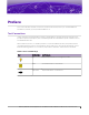
Preface This section describes the text conventions used in this document, where you can find additional information, and how you can provide feedback to us. Text Conventions Unless otherwise noted, information in this document applies to all supported environments for the products in question. Exceptions, like command keywords associated with a specific software version, are identified in the text. When a feature, function, or operation pertains to a specific hardware product, the product name is used.
Text Conventions Preface Table 1: Notes and warnings (continued) Icon Notice type Alerts you to... Caution Risk of personal injury, system damage, or loss of data. Warning Risk of severe personal injury. Table 2: Text Convention Description screen displays This typeface indicates command syntax, or represents information as it appears on the screen. The words enter and type When you see the word enter in this guide, you must type something, and then press the Return or Enter key.
Providing Feedback Preface Providing Feedback The Information Development team at Extreme Networks has made every effort to ensure the accuracy and completeness of this document. We are always striving to improve our documentation and help you work better, so we want to hear from you. We welcome all feedback, but we especially want to know about: • • • Content errors, or confusing or conflicting information. Improvements that would help you find relevant information in the document.
Subscribe to Service Notifications Preface Subscribe to Service Notifications You can subscribe to email notifications for product and software release announcements, Vulnerability Notices, and Service Notifications. 1. Go to www.extremenetworks.com/support/service-notification-form. 2. Complete the form (all fields are required). 3. Select the products for which you would like to receive notifications. Note You can modify your product selections or unsubscribe at any time. 4. Select Submit.
Overview The guide describes how to configure and deploy the Extreme Campus Controller VE6120 and VE6125 Virtual Appliances. This guide is a reference for system administrators who install and manage the VE6120 and VE6125 Virtual Appliances. Any administrator performing tasks described in this guide must have an account with administrative privileges. VE6120/VE6125 Virtual Appliances Installation Guide VMware® Platform for version 5.16.
Virtual Appliance Deployment Deployment Requirements on page 10 Connectivity Requirements on page 11 Download a VE6120/VE6125 Image on page 12 This section provides an overview of the requirements for the Extreme Campus ControllerVirtual Appliances VE6120 and VE6125 deployments. It explains how to install the appliances on a VMware® vSphere™ server (ESXi™) and how to run the initial configuration wizard. Deployment Requirements The VE6120/VE6125 are packaged in the .ova file format defined by VMware.
Connectivity Requirements Virtual Appliance Deployment • XLarge is the default and only configuration available for VE6125.
Download a VE6120/VE6125 Image • Virtual Appliance Deployment The vSwitch must be configured to accept any VLAN tag traffic and forward it without changing or removing the VLAN tags. Although configuring the necessary vSwitches does not have to be done before installing the appliance, the installation process will be simpler if it is.
Virtual Appliance Deployment Install and Deploy the Virtual Appliance Image Procedure 1. Launch a web browser and enter the vSphere address to access the vSphere application. The Web Client login screen displays. Figure 1: VMware vSphere Web Client Login Screen 2. On the VMware vSphere Web Client login screen: • Enter the User name and Password of an account that has full administrative access to the vSphere (ESXi) server. • Click Login.
Install and Deploy the Virtual Appliance Image Virtual Appliance Deployment Procedure 1. From the Navigator tab in the vSphere Web Client, right-click the host machine and select Deploy OVF Template. Figure 2: Deploy OVF Template option Note Even though the VE6120 is distributed in the .ova file format, it is compatible with the menu option of alternate .ovf format. 2. On the Deploy OVF Template window: • 14 Select Browse to select the VE6120 .
Virtual Appliance Deployment Install and Deploy the Virtual Appliance Image Figure 3: Deploy OVF Template Window Or • You can select a source URL to download and install the OVA file. VE6120/VE6125 Virtual Appliances Installation Guide VMware® Platform for version 5.16.
Install and Deploy the Virtual Appliance Image Virtual Appliance Deployment 3. On the Name and Location screen, type a name for the VE6120, select a datacenter folder, and select Next. Select a resource screen is displayed. Note The name you type will be used in the vSphere client’s inventory list. It does not have to be the same name as the hostname of the VE6120/VE6125 appliance. Figure 4: Name and Location screen 16 VE6120/VE6125 Virtual Appliances Installation Guide VMware® Platform for version 5.
Virtual Appliance Deployment Install and Deploy the Virtual Appliance Image 4. On the Select a resource screen, select a host server, and then select Next. The Review details screen is displayed. Figure 5: Select a resource screen VE6120/VE6125 Virtual Appliances Installation Guide VMware® Platform for version 5.16.
Install and Deploy the Virtual Appliance Image Virtual Appliance Deployment 5. On the Review details screen, review the information and select Next.Select storage screen is displayed. Note You can select Back to modify any of the previous settings. Figure 6: Review details screen 6. On the Select storage screen: a. Select virtual disk format as Thick provision. This is the default virtual disk format. Note Thick provision format allocates storage immediately.
Virtual Appliance Deployment Install and Deploy the Virtual Appliance Image 7. On the Select networks screen, map the virtual appliance ports to the virtual networks that are deployed on the host server. For each Source Network, select a corresponding Destination Network. Table 5: Network Selection Source Network Destination Network/ Description VM Network MGMT-63/Management port Port 2 Internal 1 Port 1 450-P8 Select Next. The Ready to complete screen is displayed. 8.
Install and Deploy the Virtual Appliance Image Virtual Appliance Deployment Figure 8: Progress bar What to Do Next When the deployment has completed successfully, select Close. 20 VE6120/VE6125 Virtual Appliances Installation Guide VMware® Platform for version 5.16.
Virtual Appliance Configuration Access the Virtual Appliance Console on page 21 Configure the VE6120/VE6125 using the Basic Configuration Wizard on page 25 Set up the VE6120/VE6125 Appliance using the Basic Configuration Wizard on page 25 Upgrade the VE6120/VE6125 Software on page 29 Set Up the Virtual Appliance to Accept USB Flash Drives on page 31 Generate and Install the Activation Package on page 36 Subscription License on page 38 Permanent Capacity License on page 38 After the Virtual Appliance has bee
Access the Virtual Appliance Console Virtual Appliance Configuration Procedure 1. Launch a web browser and enter vSphere address to open the vSphere web client application. The VMware vSphere Web Client login screen is displayed. Figure 9: VMware vSphere Web Client Login Screen 2. On the VMware vSphere Web Client login screen: 22 • Enter the User name and Password of an account that has full administrative access to the vSphere (ESXi) server. • Click Login.
Virtual Appliance Configuration Access the Virtual Appliance Console 3. On the vSphere Web Client screen, in the left Navigator pane, expand the host mode, right-click the Virtual Appliance and select Power > Power On. Figure 10: vSphere Web Client Power On option Note If the Power On option is greyed out, press the bar. icon on the vSphere Web Client tool The Green icon indicates that the virtual appliance is powered on.
Access the Virtual Appliance Console Virtual Appliance Configuration 4. After the Virtual Appliance has been started and completes its boot process, right-click the appliance name, and from the drop-down menu, click Open Console. Figure 11: Open Console option The VE6120 Command Line Interface (CLI) opens in a new window. 5. Enter your login credentials. Note Click inside the console window once or twice to make the window interactive. If the prompt is not visible, press [Enter].
Virtual Appliance Configuration Configure the VE6120/VE6125 using the Basic Configuration Wizard Figure 12: VE6120's Command Line Interface (CLI) Configure the VE6120/VE6125 using the Basic Configuration Wizard The Extreme Campus Controller software provides a Basic Configuration Wizard that can help administrators configure the minimum settings necessary to deploy a fully functioning VE6120/VE6125 appliance on a network.
Virtual Appliance Configuration Current Data Port Settings Procedure 1. After logging into the CLI of VE6120/VE6125, you will be prompted to change the admin password. To begin the admin password setup, press Enter. The Admin password Configuration screen is displayed. a. To change the password for the admin account, press Enter. b. Enter the new password for the admin account. Note The password must be between 8-24 characters. c. Repeat the new password for the admin account and press Enter.
Virtual Appliance Configuration Current Host Attributes Current Host Attributes About This Task To set up the current host attributes, Procedure 1. Press Enter to change the Host Attributes. 2. Press Enter to enter the host name for the application. 3. Type Y to set up a dedicated Admin port for out-of-band management. The default option is no. A note is displayed that the Admin port does not allow device registration. 4. Type the IP address in the following format xx.xx.xx.
Virtual Appliance Configuration Current Time Settings 3. Pick a number according to the region numbers that is displayed on screen to pick you continent. Then, enter a number that corresponds to the Region. You can enter n to move down the list, or p to move up the list. To go back to the Region selection, press c. 4. Press Enter to run NTP as a client. 5. Provide the fully qualified domain name of the NTP server. Press Enter. 6. You are prompted to enter a second NTP server and the default option is y.
Virtual Appliance Configuration Upgrade the VE6120/VE6125 Software Upgrade the VE6120/VE6125 Software About This Task If you are not installing the latest Extreme Campus Controller release, you need to upgrade the software to the latest patch release. Procedure 1. Go to the Extreme Networks Support site and download the most recent Extreme Campus Controller software patch. 2.
Upgrade the VE6120/VE6125 Software Virtual Appliance Configuration 5. To add the image file, select the plus icon. Figure 15: Upgrade section The Copy Upgrade Image window is displayed. 6. To copy an upgrade or backup image to Extreme Campus Controller, configure the following parameters: Image Type Indicates the type of image file used. Valid values are: • • Upgrade Backup Destination Destination of the uploaded image file: • • Local Flash (The Flash drive must be mounted.
Virtual Appliance Configuration Perform a Backup What to Do Next For more information about the Software Upgrade options, see the Extreme Campus Controller User Guide. Perform a Backup The backup and restore procedure is limited to configuration files and, optionally, logs and audit files. A system backup is a full system snapshot rescue file (*-rescue-user.tgz). Creating a rescue file is an option during the system upgrade process.
Set Up the Virtual Appliance to Accept USB Flash Drives Virtual Appliance Configuration 2. Insert the flash drive into a USB port on the host. Note The vSphere client application requires that a USB device be plugged in before it can be added to a virtual machine. 3. Log in to the vSphere client using an account that grants full administrative access to the VE6120. 4. From the list of guest operating systems (virtual machines), right-click on VE6120, and from the drop-down menu, select Edit Settings.
Virtual Appliance Configuration Set Up the Virtual Appliance to Accept USB Flash Drives 5. In the Virtual Hardware window, select Host USB Device from the drop-down, and click Add. Figure 17: Host USB Device Selection 6. If running vSphere and a USB device has been inserted and is not assigned to another guest, the USB Device option will be listed. Select that option and click OK. The USB Device dialog appears.
Manage the Flash Memory Virtual Appliance Configuration 8. Review the settings and then click Finish to add the USB device to VE6120 or click Cancel to abort the operation. The Virtual Machine Properties dialog displays that the USB device is in the process of being added to the virtual machine. The new USB device will be shown in bold and “adding” appears after the USB device name. 9. Click OK to save the configuration. 10.
Virtual Appliance Configuration Manage the Flash Memory 2. In the left pane, from the Administration drop-down, select System > Maintenance > External Flash option. Use the Mount/Unmount options to mount and unmount flash memory respectively. Figure 18: Flash memory maintenance window VE6120/VE6125 Virtual Appliances Installation Guide VMware® Platform for version 5.16.
Virtual Appliance Configuration Remove the Flash Drive Remove the Flash Drive About This Task Follow these steps to remove the flash drive. Note The Virtual Appliance can be in service when the USB flash drive is assigned to it using the vSphere client. Within a few seconds of the USB flash drive being assigned to it, the VE6120 will detect the flash drive and mount it for use. Procedure 1. When you are ready to remove the USB Flash drive, click Un-Mount from the Maintenance page. 2. Remove the drive. 3.
Virtual Appliance Configuration Install the Activation Package 5. On the Voucher Details page, select Generate Activation Key. Figure 19: Generate Activation Key 6. 7. 8. 9. Provide the Locking ID for the Extreme Campus Controller that will be activated. Check the box to accept Terms and Conditions and select Submit. The Activation package is generated, and the Save As dialogue displays. Download the Activation Package to your local machine.
Virtual Appliance Configuration Subscription License Subscription License Learn about Subscription Licensing. Subscription licensing is available for Extreme Campus Controller for both access point and switch management. Upon purchase of a new Extreme Campus Controller you will receive a welcome email and activation instructions.
Virtual Appliance Configuration Permanent Capacity License Procedure 1. Go to the Support portal to generate an Activation Package. For more information, see Generate and Install the Activation Package on page 36. 2. From the Support portal, obtain your capacity keys. For more information, see Obtain an Apply a Capacity Key on page 40. There is no connection to the licensing server when an Activation Package for Permanent Capacity Licensing is installed.
Obtain an Apply a Capacity Key Virtual Appliance Configuration Obtain an Apply a Capacity Key About This Task Procedure 1. Obtain a voucher from the Extreme Networks Support portal. 2. Log into the Extreme Networks Support portal to redeem the voucher. 3. 4. 5. 6. 7. The Extreme Networks Support portal presents the Capacity key. On the Extreme Campus Controller, go to Admin > License. Select the Permanent Capacity License link. Next to the Licensed Capacity field, select the plus sign.
Configure vSwitches for the Virtual Appliance Create a New Virtual Switch or Port Group on the ESXi Server on page 41 Configuring the Virtual Switch for Promiscuous Connections on page 44 Configure the Virtual Switch for Jumbo Frames Support on page 47 The Virtual Appliance has some specific requirements on the virtual switches (vSwitch) to which its data plane ports are connected. The following section explains how to create a vSwitch on an ESXi host that satisfies these requirements.
Create a New Virtual Switch or Port Group on the ESXi Server Configure vSwitches for the Virtual Appliance 4. Select the globe icon to Add host networking. Figure 22: How to add a virtual switch 5. Select the connection type: Select Virtual Machine Port Group for a Standard Switch. 6. Select target device:. You can create a new switch or create a new port group on an existing switch. • To create a port group on an existing switch: a. Select, Select an existing standard switch. b.
Configure vSwitches for the Virtual Appliance Create a New Virtual Switch or Port Group on the ESXi Server Figure 23: Adding network adapters e. On the Create a Standard Switch dialog, select Next. 7. Connection settings: • • Provide a network label for the switch or port group. VLAN ID — All (4095) 8. Ready to complete: Review the settings and select Finish. Figure 24: Ready to complete VE6120/VE6125 Virtual Appliances Installation Guide VMware® Platform for version 5.16.
Configuring the Virtual Switch for Promiscuous Connections Configure vSwitches for the Virtual Appliance 9. The new switch is listed in the Virtual switches list. A diagram of the Port Groups and Physical Adapters displays. Figure 25: Switch Diagram What to Do Next Next, configure the virtual switch for promiscuous connections. Configuring the Virtual Switch for Promiscuous Connections About This Task ESXi virtual switches collect ports into port groups.
Configure vSwitches for the Virtual Appliance Configuring the Virtual Switch for Promiscuous Connections 3. On the right pane, select Networking > Virtual switches, and select a switch from the list. Figure 26: Switch Diagram 4. Select the pencil icon to edit properties: • To configure properties for the entire switch, select switch in the switch list, then select the pencil icon above the list.
Configuring the Virtual Switch for Promiscuous Connections Configure vSwitches for the Virtual Appliance Figure 27: Editing properties 5. On the Edit Settings dialog, select the Security tab, and set all options to Accept. 6. Select OK to close the Edit Settings dialog. Figure 28: Promiscuous mode setting 46 VE6120/VE6125 Virtual Appliances Installation Guide VMware® Platform for version 5.16.
Configure vSwitches for the Virtual Appliance Configure the Virtual Switch for Jumbo Frames Support Configure the Virtual Switch for Jumbo Frames Support About This Task The jumbo frames feature enables the configuration of physical Maximum Transmission Unit (MTU) sizes up to 1800 bytes on the access point and appliance Ethernet data plane ports. The Admin port, all protocols, and interfaces continue to use the standard MTU size of 1500 bytes.
Configure the Virtual Switch for Jumbo Frames Support Configure vSwitches for the Virtual Appliance 4. Select edit settings. Figure 30: Virtual switch properties information window 5. Set the MTU to 1800. 6. Select Save. 48 VE6120/VE6125 Virtual Appliances Installation Guide VMware® Platform for version 5.16.
Configure a Virtual Machine to Gain Networking Performance About This Task Configuring a virtual machine to gain more networking performance allows you to increase the networking throughput, especially if you use 10 Gbps or faster NICs on the server. Note Perform this task after every .ova deployment since the settings cannot be exported with an .ova image. vSphere uses single receive thread and single transmit thread, regardless of the number of virtual devices configured on it.
Configure a Virtual Machine to Gain Networking Performance 2. Select VM Options. Figure 31: VM options tab 3. Expand the Advanced option. 50 VE6120/VE6125 Virtual Appliances Installation Guide VMware® Platform for version 5.16.
Configure a Virtual Machine to Gain Networking Performance 4. Select Edit Configurations next to the Configuration Parameters option. Figure 32: Edit configuration option The Configuration Parameters window opens. VE6120/VE6125 Virtual Appliances Installation Guide VMware® Platform for version 5.16.
Configure a Virtual Machine to Gain Networking Performance 5. Select Add parameter to add an entry. Figure 33: Configuration Parameters window 6. Set the following parameters in the Configuration Parameters window. Table 7: Configuration parameters entries Key Value For Port 1: • ethernet1.ctxPerDev 1 For Port 2: • ethernet2.ctxPerDev 1 Note The "X" in ethernetX.ctxPerDev command is replaced with the vNIC number.
Configure a Virtual Machine to Gain Networking Performance 7. Select OK to add the configuration parameter. 8. Select Save to save the configuration parameter. 9. Turn on the virtual machine. VE6120/VE6125 Virtual Appliances Installation Guide VMware® Platform for version 5.16.
Shut Down and Restart a Virtual Machine Shut Down and Restart a Virtual Machine Using the Graphical User Interface (GUI) on page 54 Shut Down and Restart a Virtual Machine on a ESXi server on page 55 About This Task You need to shut down a virtual machine before configuring it to gain more networking performance. The following task will outline the various ways through which you can shut down and reboot a virtual machine.
Shut Down and Restart a Virtual Machine Shut Down and Restart a Virtual Machine on a ESXi server Shut Down and Restart a Virtual Machine on a ESXi server About This Task You can shut down and restart a virtual machine through the ESXi server. Procedure 1. To shut down the virtual machine, right-click the virtual machine listed under Virtual Machines, select Guest OS > Shut down. 2. To restart the virtual machine, right-click the virtual machine listed under Virtual Machines, select Guest OS > Restart.
Index B S backup backup config 31 backup schedule 31 perform a backup 31 store backup file 31 Subscription License 38 support, see technical support C configure a virtual machine gain networking performance 49 configure vSwitches 41 conventions notice icons 5 text 5 copy backup 31 T technical support contacting 7, 8 U upload method 31 V E virtual machine reboot 54 restart 54 shut down 54 virtual switch configuration 47 virtual switch for promiscuous connections 44 vSphere client login 12 vSphere we