Extreme Campus Controller Smart RF Reference Guide Version 5.46.
Copyright © 2021 Extreme Networks, Inc. All rights reserved. Legal Notice Extreme Networks, Inc. reserves the right to make changes in specifications and other information contained in this document and its website without prior notice. The reader should in all cases consult representatives of Extreme Networks to determine whether any such changes have been made. The hardware, firmware, software or any specifications described or referred to in this document are subject to change without notice.
Table of Contents Preface...................................................................................................................................4 Text Conventions.......................................................................................................................................................... 4 Documentation and Training.................................................................................................................................. 5 Help and Support......
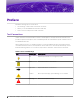
Preface Read the following topics to learn about: • • • The meanings of text formats used in this document. Where you can find additional information and help. How to reach us with questions and comments. Text Conventions Unless otherwise noted, information in this document applies to all supported environments for the products in question. Exceptions, like command keywords associated with a specific software version, are identified in the text.
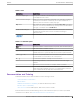
Documentation and Training Preface Table 2: Text Convention Description screen displays This typeface indicates command syntax, or represents information as it is displayed on the screen. The words enter and type When you see the word enter in this guide, you must type something, and then press the Return or Enter key. Do not press the Return or Enter key when an instruction simply says type. Key names Key names are written in boldface, for example Ctrl or Esc.
Preface Help and Support Help and Support If you require assistance, contact Extreme Networks using one of the following methods: Extreme Portal Search the GTAC (Global Technical Assistance Center) knowledge base; manage support cases and service contracts; download software; and obtain product licensing, training, and certifications. The Hub A forum for Extreme Networks customers to connect with one another, answer questions, and share ideas and feedback.
Preface Send Feedback • • Improvements that would help you find relevant information. Broken links or usability issues. To send feedback, do either of the following: • • Access the feedback form at https://www.extremenetworks.com/documentation-feedback/. Email us at documentation@extremenetworks.com. Provide the publication title, part number, and as much detail as possible, including the topic heading and page number if applicable, as well as your suggestions for improvement.
About Smart RF in Extreme Campus Controller Off-Channel Scanning on page 8 Channel and Power Selection on page 9 Recovery Features on page 10 Self Monitoring At Run Time RF Management (Smart RF) is an ExtremeWireless WiNG™ innovation designed to simplify RF configurations for new deployments, while providing on-going optimization as the RF environment changes over time.
About Smart RF in Extreme Campus Controller Channel and Power Selection every 6 seconds to monitor the RF environment for each channel. This is configurable.
About Smart RF in Extreme Campus Controller Recovery Features Each channel and power parameter is fully configurable within the Smart RF Policy, enabling an administrator to tweak the system to suit their specific wireless deployment needs. For example, administrators can modify the Smart RF policy to exclude DFS channels or lower the minimum and maximum power values for high-density deployments. By default, Smart RF will assign radios a power value between 4 dBm and 17 dBm, a 20 MHz channel to each 2.
About Smart RF in Extreme Campus Controller Interference Recovery AP in a coverage area fails or becomes faulty, the administrator will need to replace the failed AP to permanently remediate the problem. With Interference Recovery, it is possible that the interfering APs are not owned or managed by the company or division. In this case, Smart RF will adjust the channels and power values on the Smart RF managed radios to provide the best possible RF environment around the interfering devices.
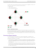
Coverage Hole Recovery About Smart RF in Extreme Campus Controller radio drops below a defined power threshold, one or more Smart RF-managed radios can increase their power to compensate for the coverage loss. Neighbor recovery is enabled by default and requires a minimum of four APs to function. Figure 4: Neighbor Recovery Note A Smart RF managed radio will only change power if a power difference of +/-3 is necessary. The power adjustment can also be >3.
About Smart RF in Extreme Campus Controller Coverage Hole Recovery Figure 5: Coverage Hole Recovery Extreme Campus Controller Smart RF Reference Guide for version 5.46.
Smart RF Policy Basic Configuration on page 14 Channel and Power on page 16 Scanning Configuration on page 18 Recovery on page 20 Select Shutdown on page 24 Enabling Smart RF requires that you define a Smart RF Policy that is assigned to one or more device groups. By default, at the device group level, you configure each radio to use Smart RF for both channel and transmit power assignments.
Smart RF Policy Basic Configuration Figure 6: Basic tab The Basic Settings parameters are used to determine the Off-Channel Scanning (OCS) aggressiveness used by Smart RF for monitoring and configuration. Changing the Smart RF Sensitivity modifies values in the Scanning Configuration, Neighbor Recovery, Interference Recovery, and Coverage Hole Recovery screens. A best practice is to use the default Medium Sensitivity. It has been proven to work well in retail, office, and warehouse environments.
Smart RF Policy Channel and Power Channel and Power The Channel and Power screen in the Smart RF Policy includes the following configuration sections: • Power Settings – Determine the minimum and maximum transmit power values assigned to Smart RF managed radios. • Channel Settings – Determine the pool of channels and channel widths assigned to the Smart RF managed radios.
Channel and Power Smart RF Policy 2.4 GHz radios are assigned a 20 MHz wide channel, and the 5 GHz and 6 GHz radios are assigned an 80 MHz wide channel. Note The 80 MHz wide channel is supported by the 802.11ac/ax radios only. • 2.4 GHz Radios – Smart RF will assign a 20 MHz wide channel (1, 6, or 11) to each Smart RF managed radio. • 5 GHz Radios – Smart RF will assign a permitted 20 MHz, 40 MHz, 80 MHz, or 160 MHz channel, provided that the AP model supports 160 MHz.
Understanding Smart RF and Channel Width Smart RF Policy Related Topics Understanding Smart RF and Channel Width on page 18 NEW! Understanding Smart RF and Channel Width Extreme Campus Controller Smart RF can ensure that the operating channel width does not conflict with radio band compliance limitations. Your channel width selection is considered when determining the optimum channel width, but it is not guaranteed.
Scanning Configuration Smart RF Policy If the deployment includes wireless devices that support PS or Voice, some Smart RF-managed radios may not be able to go off-channel for an extended period of time, which means those radios may not have the current interference or neighbor data. Scanning Configuration The Scanning Configuration determines the Off-Channel Scanning (OCS) configuration parameters assigned to the Smart RF managed radios.
Smart RF Policy Recovery awakens at the DTIM interval. If set to Strict, the Smart RF-managed radios do not perform an offchannel scan when a wireless client in Power Save state is detected. This parameter may be set to Strict in an environment where off-channel scanning may interfere with the DTIM and clients waking to receive data. For example, warehouse environments related to logistics and shipping where there may be hundreds of hand-held devices scanning thousands of packages in a given shift.
Recovery Smart RF Policy • Coverage Hole Recovery – Determines the thresholds and intervals for the Coverage Hole Recovery feature. Figure 10: Neighbor Recovery settings Hold Time The Power Hold Time parameter determines the time in seconds that a Smart RF- managed radio waits between two power changes. By default, the Power Hold Time parameter value is set to 0 (disabled) when the Sensitivity is set to Medium on the Basic Configuration screen.
Smart RF Policy Recovery Controller. Based on Off-Channel Scanning (OCS) Sample Count in the Scanning and Configuration screen, an average RSSI for each neighbor is determined from the overall attenuation of the neighbors. The attenuation plus power threshold is the power setting. If a neighbor attenuation is calculated at 80, and the threshold is set to -70, the radio power will be set to 10 (80 +(-70) = 10).
Recovery Smart RF Policy Figure 11: Interference Recovery tab Channel Hold Time The minimum amount of time between two channel changes due to interference on a Smart RF managed radio. The default is 30 minutes when you select a Medium Sensitivity setting. Client Threshold The number of wireless clients that a Smart RF managed radio will not perform a channel change due to interference. The default value is 50 clients when you select a Medium Sensitivity setting. Channel Switch Delta (2.
Smart RF Policy Select Shutdown Figure 12: Coverage Hole Recovery parameters Related Topics Basic Configuration on page 14 Select Shutdown The Select Shutdown feature is used to reduce the Co-Channel Interference (CCI) on 2.4 GHz radios in deployments that were designed for 5 GHz. Such deployments are too dense for the number of 2.4 GHz radios. Therefore, radios can be safely shut down to reduce the CCI.
Select Shutdown Smart RF Policy Figure 13: Select Shutdown settings Figure 14: Select Shutdown parameters Related Topics Basic Configuration on page 14 Extreme Campus Controller Smart RF Reference Guide for version 5.46.
RF Domain Smart RF Policies are assigned to radios at the device group level. Each device group is configured with one Smart RF Policy. Use the Extreme Campus Controller user interface to assign a Smart RF Policy to a device group: 1. Go to Configure > Sites > Device Groups. 2. Select a device group or select Add. 3. Select RF Management. Figure 15: RF Management on Device Group tab 26 Extreme Campus Controller Smart RF Reference Guide for version 5.46.
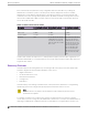
Verification and Troubleshooting Channel and Power Assignments on page 27 Smart RF Widgets on page 28 Channel Inspector Interference Report on page 29 Neighbor List on page 30 Energy Graphs on page 31 Smart RF History on page 32 Smart RF charts are available in Extreme Campus Controller to help verify successful Smart RF functionality and to assist in troubleshooting. 1. Go to Monitor > Devices > Access Points. 2. Select an AP, and then select the Smart RF tab.
Verification and Troubleshooting Smart RF Widgets Smart RF Widgets The following widget reports for each radio are available from the AP Smart RF tab: Note The Smart RF tools reflect data available for channels that are selected in the Channel Plan when Smart RF is enabled on the radio. • Mitigation.
Verification and Troubleshooting Channel Inspector Interference Report To display more details for a specific channel, select a row in the widget. The Channel Inspector Interference Report displays. • Neighbor List. Indicates channel occupancy and neighboring channels. ◦ Neighbor APs are identified by both the SSID and BSSID. ◦ The channel width for each neighbor AP is displayed, and it is an option to display the AP security setting.
Verification and Troubleshooting Neighbor List The channel data generated from Smart RF populates the report. The report is generated from the last channel scan. The report lists visible BSSID and SSID data with RF measurements. Note Smart RF data is available only when Smart RF is enabled and only for channels that are in the Smart RF channel plan.
Verification and Troubleshooting Energy Graphs Each Smart RF managed radio captures the MAC address, Channel, and RSSI of each neighbor or interfering wireless AP that the selected AP sees. The Neighbor List can be useful when trying to resolve RF issues.
Verification and Troubleshooting Smart RF History Figure 18: Channel Energy Graph per AP Smart RF History Extreme Campus Controller maintains a history of all Smart RF events that can be displayed in real-time using the Extreme Campus Controller user interface. Go to Tools > Logs > AP Logs. The Smart RF History includes all Smart RF related events including: • • • radios being added channel and power changes Neighbor Recovery, Interference Recovery, and Coverage Hole Recovery events.
Verification and Troubleshooting Smart RF History Figure 19: Smart RF History from AP Logs Extreme Campus Controller Smart RF Reference Guide for version 5.46.
Index A P announcements 6 product announcements 6 B R Basic settings 14 recovery features 10 Recovery settings 20 RF Domain 26 RF Management Smart RF widgets 28 C Channel and Power assignments 27 Channel and Power Distribution 27 channel and power selection 9 Channel and Power settings channel width 18 Channel Inspector Interference Report 29 conventions notice icons 4 text 4 Coverage Hole Recovery 12 D documentation feedback 6 location 5 E S Scanning Configuration 18 Select Shutdown settings 24