Extreme Defender Application Deployment Guide Version 3.
Copyright © 2020 Extreme Networks, Inc. All rights reserved. Legal Notice Extreme Networks, Inc. reserves the right to make changes in specifications and other information contained in this document and its website without prior notice. The reader should in all cases consult representatives of Extreme Networks to determine whether any such changes have been made. The hardware, firmware, software or any specifications described or referred to in this document are subject to change without notice.
Table of Contents Preface........................................................................................................................................................................................v Conventions.....................................................................................................................................................................v Text Conventions...........................................................................................................
Table of Contents Example: DICOM Client Whitelist Role................................................................................................... 37 Layer 7 Application Rules......................................................................................................................................38 Create Layer 7 Application Rules..............................................................................................................39 Security Profile Creation Workflow.............
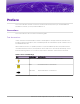
Preface This section describes the text conventions used in this document, where you can find additional information, and how you can provide feedback to us. Conventions This section discusses the conventions used in this guide. Text Conventions Unless otherwise noted, information in this document applies to all supported environments for the products in question. Exceptions, like command keywords associated with a specific software version, are identified in the text.
Text Conventions Preface Table 1: Notes and warnings (continued) Icon Notice type Alerts you to... Caution Risk of personal injury, system damage, or loss of data. Warning Risk of severe personal injury. Table 2: Text Convention Description screen displays This typeface indicates command syntax, or represents information as it appears on the screen. The words enter and type When you see the word enter in this guide, you must type something, and then press the Return or Enter key.
Providing Feedback Preface Providing Feedback The Information Development team at Extreme Networks has made every effort to ensure the accuracy and completeness of this document. We are always striving to improve our documentation and help you work better, so we want to hear from you. We welcome all feedback, but we especially want to know about: • • • Content errors, or confusing or conflicting information. Improvements that would help you find relevant information in the document.
Subscribe to Service Notifications Preface Subscribe to Service Notifications You can subscribe to email notifications for product and software release announcements, Vulnerability Notices, and Service Notifications. 1. Go to www.extremenetworks.com/support/service-notification-form. 2. Complete the form (all fields are required). 3. Select the products for which you would like to receive notifications. Note You can modify your product selections or unsubscribe at any time. 4. Select Submit.
About Extreme Defender for IoT Solution Deployment Before You Begin on page 9 Network Deployment Options on page 10 Managed Device Attachment on page 10 The Extreme Defender for IoT solution consists of the following elements for deployment: • • • ExtremeCloud™ Appliance Extreme Defender Application SA201 adapter or AP3912i The Extreme Defender Application is installed on the ExtremeCloud Appliance docker container platform and provides restricted provisioner / administrator access.
Network Deployment Options About Extreme Defender for IoT Solution Deployment For more information, see the Installation video at https://extremenetworks.com/documentation/ extremecloud-appliance. • You must be familiar with managed device provisioning (SA201 adapter or AP3912i) and policy configuration. • You must have detailed knowledge of the network switching infrastructure, which may include: ◦ Access layer VLAN and IP subnet configuration.
About Extreme Defender for IoT Solution Deployment Local VLAN Attachment Model If Fabric Attach is enabled on the Extreme Networks access switch to which the SA201 adapter or AP3912i is connected, there are two options for automating the management plane VLAN ID using Untagged or Tagged frames between the SA/AP and the switch. ExtremeCloud Appliance discovery options are available: such as DHCP Option 43/60, DHCP Option 78, and SLP.
Fabric Connect with Fabric Attach Model About Extreme Defender for IoT Solution Deployment Figure 3: IPSec Tunnel Overlay model Fabric Connect with Fabric Attach Model Figure 4 illustrates the Fabric Connect core Fabric Attach model highlighting the attachment of different IoT device types. IoT device traffic is switched at the SA201 adapter or AP3912i directly onto a local VLAN and Fabric service that has been dynamically created by FA based on the security profile for the specific IoT device.
Download and Install Extreme Defender Application Download Defender Application on page 13 Install Defender on page 14 Generate API Key on page 15 Upload the API Key File on page 15 Run Defender Application on page 16 Configuration Wizard on page 17 Licensing on page 20 User Accounts on page 21 Download Defender Application You can find the Defender Application docker app on the Extreme Networks support portal. 1.
Download and Install Extreme Defender Application Install Defender 3. Select Defender for IoT for a list of product versions and release notes. Figure 6: Defender Application downloads and release notes Install Defender Note Before you can access Extreme Defender Application you must install ExtremeCloud Appliance and generate an API key for access to Defender. For more information, refer to https://extremenetworks.com/documentation/extremecloud-appliance.
Download and Install Extreme Defender Application Generate API Key Generate API Key Note When running more than one Extreme Campus Controller application that uses an API key file, you need only one generated API key. 1. 2. 3. 4. Log into Extreme Campus Controller with administrator credentials. Go to Administration > Accounts. Select a user account. From the API Keys field, select Generate New API Key. The key is generated. The API Key dialog displays. Figure 7: API Key dialog 5.
Download and Install Extreme Defender Application Run Defender Application To upload a generated API key file: 1. Log into ExtremeCloud Appliance with full administrator credentials. 2. Go to Administration > Applications and select . 3. Select the Configuration Files tab. 4. Select api-keys.json, and then select the upload icon 5. Upload the API key file one of the following ways: • • . Click the Choose File box and navigate to the downloaded API key file.
Download and Install Extreme Defender Application Configuration Wizard Configuration Wizard When you log in to Extreme Defender Application for the first time, you are prompted with initial configuration options. Figure 8: Defender Initial Configuration Take the following steps: 1. Select a Country and Time Zone value from the drop-down lists. Specify the values that correspond to your AP licensing domain. 2. (Optional) You can rename the default Defender site. 3.
Configuration Reset Download and Install Extreme Defender Application DFNDR_SITE. You can specify a unique name. 2 device groups • • DFNDR_Devices for AP3912i access points. DFNDR_SA201_Devices for SA201 adapters. 1 network service DFNDR_Service 2 adoption rules One rule for each device group. 2 device group configuration Profiles • • DFNDR_SA201 for wired SA201 adapters DFNDR for wireless AP3912i access points.
Download and Install Extreme Defender Application Configuration Reset Before running the Configuration Wizard, you must delete these device groups or rename them on ExtremeCloud Appliance. Note It is a best practice to manually delete the DFNDR sites from ExtremeCloud Appliance before running the Defender Configuration Wizard. To run the Configuration Wizard reset: 1. Go to Administration > System > Setup. 2. Select . The Configuration Wizard dialog displays. Figure 9: Defender Configuration Wizard 3.
Download and Install Extreme Defender Application Licensing Licensing Licensing for the Defender for IoT solution is based on the number of IoT devices being protected by Defender. Extreme Defender Application allows a specific number of protected device licenses. The Licensing page displays the following information: • • • • Maximum number of supported devices for the appliance model Total number of licenses Number of licenses currently used Number of available licenses.
Download and Install Extreme Defender Application User Accounts Figure 10 shows that the maximum number of devices this Extreme Defender Application can protect is 1000. This instance has a total of 10 licenses. Devices can be MRI / CT scanner, Infusion pumps, HVAC, printer or any other IoT device. Note ExtremeCloud Appliance governs the total number of managed devices and the capacity of managed devices. Log into ExtremeCloud Appliance, then go to Administration > License.
User Accounts Download and Install Extreme Defender Application with the same tag.
Add Managed Devices Sites in Extreme Defender Application on page 23 Creating Defender Sites in ExtremeCloud Appliance on page 24 Sites in Extreme Defender Application The option to create auto-provisioning rules for new access points in the Initial Configuration Wizard automates the process of adding the SA201 adapter or AP3912i to Extreme Defender Application.
Creating Defender Sites in ExtremeCloud Appliance Add Managed Devices Creating Defender Sites in ExtremeCloud Appliance During the device activation process, Extreme Defender Application automatically creates sites and device groups on ExtremeCloud Appliance. The default name for the site is DFNDR_SITE. You can create additional Defender sites in ExtremeCloud Appliance and manually specify the site during device activation.
Include a Site in the .CSV File Add Managed Devices Select from the list of configured sites in ExtremeCloud Appliance. When you select Default, the site is assigned using the Defender adoption rules present on ExtremeCloud Appliance. This is the default value. Note Before selecting a site for device provisioning, the site and device groups must be configured on ExtremeCloud Appliance.
VLAN Configurations Bridged@AP Configuration on page 28 Bridged@AC Configuration on page 29 Fabric Attach Configuration on page 31 Determine VLAN configuration before connecting an IoT device to the network through an SA201 adapter or AP3912i. Configure VLANs from ExtremeCloud Appliance. The deployment approach for Extreme Defender Application is to apply a role that specifies the VLAN service that the associated IoT device is meant to connect to.
VLAN Configurations Figure 11: VMWare: Network Adapters connected to ExtremeCloud Appliance • FabricAttach — Utilize Fabric Attach to automatically configure switch ports that the Defender device is plugged into. Note A fully-deployed and configured Fabric Attach network is required to implement a Fabric Connect topology. With Fabric Attach, you must define the VLAN ID and I-SID (fabric service ID).
Bridged@AP Configuration VLAN Configurations Bridged@AP Configuration To configure a B@AP topology, take the following steps: 1. From ExtremeCloud Appliance, go to Configure > Policy > VLANs and click Add. 2. Configure the following parameters: Name Provide a unique name for the VLAN. Mode Select Bridged@AP — Assigned to APs, the AP bridges traffic between its wired and wireless interfaces without involving the ExtremeCloud Appliance.
VLAN Configurations Bridged@AC Configuration Figure 14: Topology using local VLAN attachment with Bridged@AP Bridged@AC Configuration To configure a B@AC topology, take the following steps: 1. From ExtremeCloud Appliance, go to Configure > Policy > VLANs and click Add. 2. Configure the following parameters: Name Provide a unique name for the VLAN. Mode Select Bridged@AC — The ExtremeCloud Appliance bridges traffic for the station through its interfaces, rather than routing the traffic.
Bridged@AC Configuration VLAN Configurations Figure 15: Bridged@AC VLAN Configuration Using the settings shown in Figure 15, IoT device traffic assigned to a role that is using “IOT_SVC-1500” will be tagged with VLAN 1500 at the SA201 adapter or AP3912i, then tunneled to ExtremeCloud Appliance and forwarded to the remote VLAN with VID1500 tag egressing the Data Port2 on ExtremeCloud Appliance. 3.
VLAN Configurations Fabric Attach Configuration Figure 17: Topology using local VLAN attachment with Bridged@AC Fabric Attach Configuration You must create new VLANs from ExtremeCloud Appliance. To configure a Fabric Attach topology, take the following steps: 1. From ExtremeCloud Appliance, go to Configure > Policy > VLANs and click Add. 2. Configure the following parameters: Name Provide a unique name for the VLAN.
Fabric Attach Configuration Figure 18: Fabric Attach VLAN Configuration Figure 19: Topology using Fabric Attach mode 32 Extreme Defender Application Deployment Guide for version 3.
Creating Policy Roles and Policy Rules for IoT Devices Automated Policy Generation on page 33 Policy Groups and Roles for IoT Devices on page 34 Create Policy Roles on page 34 Layer 7 Application Rules on page 38 Security Profile Creation Workflow on page 42 Automated Policy Generation Extreme Defender Application provides an automatic Policy Generation tool to assist with the easy creation of policy rules for IoT devices. Any IoT device can be placed into policy generation mode.
Policy Groups and Roles for IoT Devices Creating Policy Roles and Policy Rules for IoT Devices For more information about policy roles and the Defender Policy Generator, see the Extreme Defender Application User Guide at https://extremenetworks.com/documentation/defender-application. For more information about working with policy roles in ExtremeCloud Appliance, see ExtremeCloud Appliance User Guide at https://extremenetworks.com/documentation/extremecloud-appliance.
Creating Policy Roles and Policy Rules for IoT Devices Manual Role Creation Related Topics Manual Role Creation on page 35 Automatic Role Creation on page 35 Example: DICOM Client Whitelist Role on page 37 Manual Role Creation To create a role manually: 1. Log in to ExtremeCloud Appliance and go to Configure > Policy > Roles > Add. Note Roles created for access from the Extreme Defender Application must be named with the DFNDR_ prefix. 2. Configure the following parameters: Name Name of the role.
Creating Policy Roles and Policy Rules for IoT Devices Automatic Role Creation To automatically create a role for an IoT device, take the following steps: 1. Log in to Extreme Defender Application and go to Protected Devices. 2. Select an active, on-boarded device by clicking on the IP, MAC or Host name fields in the list. Note The device must be in active, on-boarded status to enable the Policy Generator tab. 3. From the Protected Device Detail, select the Policy Generator tab. 4.
Creating Policy Roles and Policy Rules for IoT Devices Example: DICOM Client Whitelist Role Example: DICOM Client Whitelist Role This topic illustrates how to manually create new roles for a DICOM (Digital Imaging and Communications in Medicine) imaging device. DICOM is a an imaging file format and network protocol. 1. Log in to ExtremeCloud Appliance. 2. Go to Configure > Policy > Roles and select Add. 3. Configure the following parameters: Name Use an appropriate name that summarizes the rule.
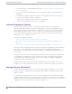
Layer 7 Application Rules Creating Policy Roles and Policy Rules for IoT Devices 5. Select New and select the rule row to edit the full rule options for Classification and Action. The following is an example of a rule to allow ICMP (Ping) between the DICOM client device and the PACS host IP subnet: • • • Action: Allow Protocol: ICMP PACS host IP subnet: 10.50.200.0/24 Figure 23: Rule to allow ICMP (Ping) between the DICOM client device and the PACS host IP subnet 6.
Creating Policy Roles and Policy Rules for IoT Devices Create Layer 7 Application Rules add a final set of Deny catchall rules. The Deny rules will deny all traffic other than traffic allowed by the specific L2- L4 rules and the application traffic (L7). Figure 27 is an example of a whitelist role that is comprised of rules from L3, L4 and L7.
Create Layer 7 Application Rules Creating Policy Roles and Policy Rules for IoT Devices Associated Profile Indicates profiles that this role is associated with. Select to modify profile association. To ensure a device profile (SA201 adapter or AP3912i) is selected to support the new role, select You will also be prompted to select the Associated Profiles when saving the role. Note Associate a role with a configuration Profile. The configuration Profile is associated with the device group.
Creating Policy Roles and Policy Rules for IoT Devices Create Layer 7 Application Rules Figure 30: ExtremeCloud Appliance DICOM role with Layer 7 Wild Card rules 6. To catch any other applications whose signatures may not be recognized by ExtremeCloud Appliance, an additional Deny rule for unknown applications is required.
Security Profile Creation Workflow Creating Policy Roles and Policy Rules for IoT Devices 7. To support selected Layer 3 / 4 rules, expand the L3, L4 (IP and Port) Rules section and select New. For an example of Layer 3 and Layer 4 rules that allow DHCP, DNS for the DICOM Client device, and allow HTTP to a specific IP subnet, see Example: DICOM Client Whitelist Role on page 37. Note As L2, L3 or L4 rules precede Layer 7, avoid classifying traffic on a broad basis, which could negate Layer 7 rules.
Creating Policy Roles and Policy Rules for IoT Devices Security Profile Creation Workflow Figure 32: Security Profile Creation Workflow Extreme Defender Application Deployment Guide for version 3.
Create Onboard Access Control Groups and Rules Create Onboard Groups in ExtremeCloud Appliance on page 44 Create Onboard Groups in Defender Application on page 45 Create Onboard Rules on page 46 Apply Security Profiles in Extreme Defender Application on page 48 We have created network policy roles under Create Policy Roles on page 34, now we will create access control groups and rules. An access control rule automates the onboarding process. It is comprised of a policy role and an access control group.
Create Onboard Access Control Groups and Rules Create Onboard Groups in Defender Application This type is used for IoT device MAC authentication to the group where a Defender Group Profile is selected against an IoT device in the Defender Protected Devices list. Group Mode For End System LDAP Host Groups only. Not applicable here.
Create Onboard Rules Create Onboard Access Control Groups and Rules Figure 34: Defender Application Onboard Group configuration 3. Within Extreme Defender Application all groups created and associated to a role automatically create an Access Control Rule within ExtremeCloud Appliance. To validate, from ExtremeCloud Appliance, go to Onboard > Rules and view the End-System Rule Conditions linking the Group Profile Policy to the Access Policy.
Create Onboard Access Control Groups and Rules Create Onboard Rules After creating a role, you can create a policy group within ExtremeCloud Appliance or Extreme Defender Application. Note Access Control Rules need to be manually created only when the role and policy group is manually created from ExtremeCloud Appliance. To create an Access Control Rule in ExtremeCloud Appliance: 1. Go to Onboard > Rules and click Add. 2. Configure the following parameters: Name Name of the rule.
Apply Security Profiles in Extreme Defender Application Create Onboard Access Control Groups and Rules Figure 36: ExtremeCloud Appliance Access Control Rule 3. Click Save. New rule displays in the Onboard Rules list. Figure 37: Defender IoT Access Control Rule — ExtremeCloud Appliance Apply Security Profiles in Extreme Defender Application Once policy roles and groups are created, we can deploy them with connected IoT devices within Extreme Defender Application.
Create Onboard Access Control Groups and Rules Selecting group from Device Details 2. From the Select a Group drop-down, select the desired group Profile to apply to the DICOM device and click OK. 3. (Optional) you can click on the device IP address, MAC address or Host name in the Protected Devices list and enter a text description for the device. 4. When Defender has assigned the group profile and policy, from the Policy tab, verify the associated group to view the MAC addresses of assigned devices.
Selecting group from Device Details Create Onboard Access Control Groups and Rules Figure 39: Selecting group from AP3912 Details tab Figure 40: Selecting group from SA201 Details tab 50 Extreme Defender Application Deployment Guide for version 3.
Modify Configuration Profile for Defender Device Groups The Extreme Defender Application Configuration Wizard automatically creates two adoption rules for an SA201 adapter or AP3912i device. As a result, any SA201 adapter or AP3912i that discovers ExtremeCloud Appliance is automatically onboarded to the appropriate device group under the DFNDR_SITE. You have the option to modify the configuration Profile for the device group in ExtremeCloud Appliance. Take the following steps: 1. Go to Configure > Sites. 2.
Modify Configuration Profile for Defender Device Groups 6. Click Save. Figure 41: SA201 Device Group Roles tab 7. If required, select the Wired Ports tab to set the port speed and duplex of the IoT device side port of an SA201 adapter or AP3912i. 52 Extreme Defender Application Deployment Guide for version 3.
Modify Configuration Profile for Defender Device Groups 8. From the Edit Profile dialog, click Advanced to view additional settings. You can enable Session persistence from the Advanced Settings dialog. Session persistence prevents the Defender adapter from rebooting when communication with ExtremeCloud Appliance is lost. Figure 42: Edit Profile Advanced Settings You have the option to create additional sites and device groups. For more information, see Sites in Extreme Defender Application on page 23.
Index A L access control rules 46 accounts 21 API key generating 15 using with Defender 15 Automatic Policy Generator 33 Layer 7 Application Rules 38, 39 licensing 20 Local VLAN Attachment model 11 B Bridged@AC configuration 29 Bridged@AP configuration 28 C Configuration Wizard 17, 18 conventions notice icons v text v D Defender Application downloading 13 supported topologies 26 Defender, running 16 device groups 23 documentation feedback vii location viii downloading 13 E Extreme Defender for IoT so
Index W warnings v whitelist role 37