ExtremeAnalytics® PV-A-305 Installation Guide 12/2019 9036589-00 Subject to Change Without Notice
Copyright © 2019 Extreme Networks, Inc. All Rights Reserved. Legal Notices Extreme Networks, Inc., on behalf of or through its wholly-owned subsidiary, Enterasys Networks, Inc., reserves the right to make changes in specifications and other information contained in this document and its website without prior notice. The reader should in all cases consult representatives of Extreme Networks to determine whether any such changes have been made.
l l l GTAC Knowledge — Get on-demand and tested resolutions from the GTAC Knowledgebase, or create a help case if you need more guidance. The Hub — A forum for Extreme customers to connect with one another, get questions answered, share ideas and feedback, and get problems solved. This community is monitored by Extreme Networks employees, but is not intended to replace specific guidance from GTAC.
Table of Contents Table of Contents 4 About This Guide 6 Engine Overview and Setup 7 Kit Contents 7 Specifications 7 Front Panel Features 9 Hard Drive LED Indicator Patterns Back Panel Features 10 11 Power Supply Status Indicator Patterns Removing and Installing the Front Bezel 11 12 Removing the Front Bezel 12 Installing the Front Bezel 13 Installing the Engine into a Rack 13 Torque Values 14 Configuration 15 Pre-Configuration Tasks 15 Configuring the ExtremeAnalytics Engine 15
Changing the Management Center Server IP Address 30 Changing the Web Service Credentials 30 Upgrading ExtremeAnalytics Engine Software 31 Reinstalling Engine Software 33 Product Regulatory and Compliance Information 35 Federal Communications Commission (FCC) Notice 35 Industry Canada, Class A 36 CE Notice 36 VCCI Notice 36 BSMI EMC Statement — Taiwan 36 Hazardous Substances 37 European Waste Electrical and Electronic Equipment (WEEE) Notice 37 Declaration of Conformity 39 5 of 39
About This Guide This document describes the installation and initial configuration of the ExtremeAnalytics PV-A-305 hardware engine. This document is intended for experienced network administrators who are responsible for implementing and maintaining communications networks.
Kit Contents Engine Overview and Setup This chapter lists the components shipped with the PV-A-305 engine, describes the front and back panels, and provides information on engine specifications. For complete regulatory compliance and safety information, refer to the document Intel® Server Products Product Safety and Regulatory Compliance, available at the following links: http://download.intel.com/support/motherboards/server/sb/g23122003_ safetyregulatory.pdf http://www.extremenetworks.
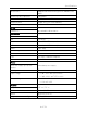
Specifications Architecture 2400 MHz Dual Ranked Registered (RDIMM) ECC DDR4 Memory module capacities 4 GB DIMMs Minimum RAM (included) 64 GB (sixteen 4 GB DIMMs) Maximum RAM 128 GB (thirty-two 4 GB RDIMMs) RAID Configuration RAID 1 with BBU Drives Hard drives One 960 GB SSD hard drive Connectors Back NIC Four RJ-45 Serial 9-pin, DTE, 16550-compatible USB Three 4-pin, USB 2.0-compliant Video 15-pin VGA Networking Two 1 GB Ethernet Front USB Two 4-pin, USB 2.
Front Panel Features PV-A-305 Environmental Specifications Parameter Limits Operating temperature +10°C (+50°F) to +35°C (+95°F) with the maximum rate of change not to exceed 10°C (+50°F) per hour Storage temperature -40°C (-40°F) to +70°C (+158°F) Storage humidity 50% to 90%, non-condensing at 28°C (82°F) Vibration, unpackaged 5 Hz to 500 Hz, 2.
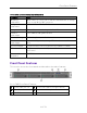
Front Panel Features Front Control Panel A System ID button w/integrated LED F System status LED B NMI button (recessed, tool required for use) G Power button w/integrated LED C Mgmt port activity LED H Hard drive activity LED D Not used I Not used E System cold reset button J Not used Hard Drive LED Indicator Patterns The hard drive has two LED indicators visible from the front of the system: one is a green LED for disk activity, and the other is amber and indicates hard drive status.
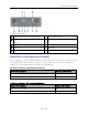
Back Panel Features Back Panel Features This section shows the back panel and describes the major features. PV-A-305 Back Panel A Power supply module #1 F Serial port B Power supply module #2 G USB 2.0 ports C eth0 H Mgmt port, out of band D eth1 I I/O Module Bay E Video connector J Riser cards The following table describes the LEDs for the RJ45 management port.
Removing and Installing the Front Bezel to maximize efficiency. Each power supply has a single bi-color LED to indicate power supply status, as described in the following table. Power Supply Status LED Indicator Patterns LED Pattern Power Supply Condition Green Output on and OK Off No AC power to all power supplies 1Hz blinking green AC present / Only 12VSB on (PS off) or PS in cold redundant state Amber AC power cord unplugged or AC power lost.
Installing the Engine into a Rack 1. Unlock the bezel if it is locked. 2. Remove the left end of the front bezel from rack handle. 3. Rotate the front bezel counterclockwise to release the latches on the right end from the rack handle. Installing the Front Bezel Note: Before installing the bezel, you must install the rack handles. See Installing the Engine into a Rack. To install the front bezel: 1. Lock the right end of the front bezel to the rack handle. 2.
Installing the Engine into a Rack Installing the Rack Handles 2. Read the installation guide included with the rack mounting kit. 3. Install the rails and mount the controller in the rack as instructed. Torque Values The following table describes the recommended torque values to use when installing the engine using standard threaded fastener machine screws and bolts. Recommended Torque Values by Screw Size Screw Size Torque in Pounds Bit Size English Metric -%5 Nominal +%5 N/A N/A 1.42 1.5 1.
Pre-Configuration Tasks Configuration Once you have installed the engine into a rack, you need to connect a monitor and a USB keyboard, connect the power cord and network cable, and power the engine on. After the engine boots and the engine installation is complete, you must go through the initial configuration process described in this chapter.
Configuring the ExtremeAnalytics Engine 1. Login as root with no password, and press [Enter]. The following screen appears: ========================================================== ====== Extreme Networks - ExtremeAnalytics Engine Welcome to the ExtremeAnalytics Engine Setup ========================================================== ====== Please enter the information as it is requested to continue with the configuration. Typically a default value is displayed in brackets.
Configuring the ExtremeAnalytics Engine Would you like to set a root password (y/n) [y]? Note: You must set a new root password. This new root password will be used by the initial user when logging in to the ExtremeAnalytics application. 3. Enter y to set the new root password. 4. Press [Enter] and enter the new password as prompted. Enter new UNIX password: Retype new UNIX password: Password updated successfully. The ExtremeAnalytics Engine Deployment screen appears. 5.
Configuring the ExtremeAnalytics Engine its own IP Address and GRE Tunnels will be configured for traffic monitoring. Suitable for feeds from Coreflow switches. 4. Manual Mode - The interface and tunneling configurations will not be modified by this script, leaving them to be manually edited by the user instead. Please select a deployment mode [2]: Note: If you select deployment mode 4, refer to the Extreme ExtremeAnalytics Deployment Guide for information on how to configure your deployment manually. 6.
Configuring the ExtremeAnalytics l Engine For deployment mode 2, proceed to step 8. 8. Specify one or more tap ports. If you have an installed optional PV-A-300-10G-UG I/O module, the ports are eth4 and eth5. For each line, type the requested configuration information and press [Enter].
Configuring the ExtremeAnalytics Engine 10. Enter the IP addresses for one or more GRE tunnels. For each line, type the requested configuration information and press [Enter]. ========================================================== ====== ExtremeAnalytics Engine GRE Configuration ========================================================== ====== Remote mirroring can be configured in Coreflow Switches using GRE tunnels. This requires a specific mirroring configuration enabled on the switches.
Configuring the ExtremeAnalytics l Address: 10.54.184.88 l Netmask: 255.255.255.0 l Gateway: 10.54.184.1 l Nameserver: 10.54.188.120 l Domain name: nac2003.com Engine 4. NIS Server/Domain: Not Configured 5. Monitor Interface Configuration: Tap Mode Interfaces: eth4, eth5 The following example shows the Confirm Network Settings screen for deployment mode 2.
Configuring the ExtremeAnalytics l Name: eth4 l Address: 10.54.211.116 l Netmask: 255.255.255.0 l Gateway: 10.54.211.1 l Name: eth5 l Address: 10.54.222.117 l Netmask: 255.255.255.0 l Gateway: 10.54.222.1 Engine 6. GRE tunnels: l 10.54.211.116/10.54.1.116 l 10.54.222.117/10.54.2.117 12. In the SNMP Configuration screen, type the requested information for each line and press [Enter].
Configuring the ExtremeAnalytics Engine ========================================================== ====== These are the current SNMP V3 settings. To accept them and complete SNMP configuration, enter 0 or any key other than the selection choices. If you need to make a change, enter the appropriate number now or run the /usr/postinstall/snmpconfig script at a later time. 0. Accept the current settings 1. SNMP User: snmpuser 2. SNMP Authentication: snmpauthcred 3. SNMP Privacy: snmpprivcred 4.
Configuring the ExtremeAnalytics Engine ========================================================== ====== NTP Servers ========================================================== ====== These are the currently specified NTP servers. Enter 0 or any key other than a valid selection to complete NTP configuration and continue. If you need to make a change, enter the appropriate number from the choices listed below. 144.131.10.120 144.131.10.121 0. Accept the current settings 1. Restart NTP server selection 2.
Configuring the ExtremeAnalytics Engine Please enter the hour of day [09]: Please enter the minutes [34]: Please enter the seconds [08]: 17. In the Use UTC screen, select whether you want the system clock to be set to use UTC. ========================================================== ====== Use UTC ========================================================== ====== The system clock can be set to use UTC. Specifying no for using UTC, sets the hardware clock using localtime.
Launching the ExtremeAnalytics Application ========================================================== ====== Modify Settings ========================================================== ====== All of the information needed to complete the installation of the ExtremeAnalytics Engine has been entered. Enter 0 or any key other than a valid selection to continue. If you need to make a change, enter the appropriate number from the choices listed below.
Adding the ExtremeAnalytics Engine from a remote client machine. 1. Open a browser window on the remote client machine and enter the Extreme Management Center Launch page URL in the following format: http://:8080/ where is the Extreme Management Center engine IP address or hostname, and 8080 is the required port number. For example, http://10.20.30.40:8080/ The Extreme Management Center Launch Page opens. 2. Enter your Extreme Management Center username and password and click Login.
Adding the ExtremeAnalytics Engine 1. Select the Configuration tab in the Analytics tab. 2. Click the Menu icon and select Add Engine.
Changing ExtremeAnalytics Engine Settings The Add ExtremeAnalytics Engine window displays. 3. Enter the IP Address of the eth0 interface and the Name of the ExtremeAnalytics engine. 4. Select the appropriate SNMP Profile from the Profile drop-down list. 5. Click OK. 6. Select Enforce Engine from the drop-down list. The ExtremeAnalytics engine is added to Management Center.
Changing ExtremeAnalytics Engine Settings This starts the network configuration script and allows you to make the required changes. You must reboot the engine for the new settings to take effect.
Upgrading ExtremeAnalytics Engine Software If you have changed the credentials in the Analytics tab and then install a new engine using the default password, you will not be able to monitor or enforce to the new engine until you change the password on the engine using this command. The credentials you enter on the engine must match the credentials specified in Analytics > Configuration. To change Web Service credentials: 1.
Upgrading ExtremeAnalytics Engine Software 5. Change the permissions on the upgrade file by entering the following command: chmod 755 purview_appliance_upgrade_to_version.bin 6. Run the install program by entering the following command: ./purview_appliance_upgrade_to_version.bin The upgrade begins automatically. The ExtremeAnalytics engine restarts automatically when the upgrade is complete.
Upgrading ExtremeAnalytics Engine Software Reinstalling Engine Software In the event a software reinstall becomes necessary, use this procedure. Be aware that this procedure reformats the hard drive and reinstalls all the engine software, the operating system, and all related Linux packages. Connect a monitor and a USB keyboard to the ExtremeAnalytics engine prior to performing these steps. 1. Download the Extreme Analytics Engine Image 64bit (ZIP) file to your system. To download an engine image: 1.
Upgrading ExtremeAnalytics Engine Software 8. Insert the USB flash drive into a USB port on the engine (see Front Panel Features). 9. Press the power button on the PV-A-305 engine. 10. Verify the USB flash drive is available as a boot option: l Press F2 to open the BIOS Setup Menu when prompted. l Press the right arrow button to select the Boot Options tab. l Select Internal EFI Shell as Boot Option #1 in the boot menu. l Select [Enabled] in the USB Boot Priority field.
Federal Communications Commission (FCC) Notice Product Regulatory and Compliance Information For complete regulatory compliance and safety information, refer to the document Intel® Server Products Product Safety and Regulatory Compliance, available at the following links: http://download.intel.com/support/motherboards/server/sb/g23122003_ safetyregulatory.pdf https://www.extremenetworks.
Industry Canada, Class A Industry Canada, Class A This Class A digital apparatus complies with Canadian ICES‐ 003. This digital apparatus does not exceed the Class A limits for radio noise emissions from digital apparatus set out in the interference‐ causing equipment standard entitled “Digital Apparatus,” ICES‐ 003 of the Canadian Department of Communications.
Hazardous Substances measures. Hazardous Substances This product complies with the requirements of Directive 2011/65/EU of the European Parliament and of the Council of 8 June 2011 on the restriction of the use of certain hazardous substances in electrical and electronic equipment. European Waste Electrical and Electronic Equipment (WEEE) Notice In accordance with Directive 2012/19/EU of the European Parliament on waste electrical and electronic equipment (WEEE): 1.
European Waste Electrical and Electronic Equipment (WEEE) For information about the available collection system, please contact Extreme Customer Support at +353 61 705500 (Ireland).
Declaration of Conformity Declaration of Conformity Application of Council Directive(s): 2004/108/EC 2006/95/EC 2011/65/EU Manufacturer’s Name: Extreme Networks, Inc.