ExtremeLocation Toolbox Guide 9036448-00 Rev AA Published August 2019
Copyright © 2019 Extreme Networks, Inc. All rights reserved. Legal Notice Extreme Networks, Inc. reserves the right to make changes in specifications and other information contained in this document and its website without prior notice. The reader should in all cases consult representatives of Extreme Networks to determine whether any such changes have been made. The hardware, firmware, software or any specifications described or referred to in this document are subject to change without notice.
Table of Contents Preface......................................................................................................................................... 4 Audience................................................................................................................................................................................... 4 Conventions..................................................................................................................................................
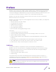
Preface ExtremeLocation is a massively scalable, enterprise grade, resilient, cloud-based location and analytics solutions from Extreme Networks. With real-time location and analytics, you can engage with your customers providing personalized experience for guests and visitors. ExtremeLocation can also be used to monitor your work flows and assets to improve your overall operation and efficiency.
Preface Conventions This section discusses the conventions used in this guide. Text Conventions The following tables list text conventions that are used throughout this guide. Table 1: Notice Icons Icon New! Notice Type Alerts you to... General Notice Helpful tips and notices for using the product. Note Important features or instructions. Caution Risk of personal injury, system damage, or loss of data. Warning Risk of severe personal injury. New Content Displayed next to new content.
Preface If you would like to provide feedback to the Extreme Networks Information Development team, you can do so in two ways: • • Use our short online feedback form at https://www.extremenetworks.com/documentationfeedback/. Email us at documentation@extremenetworks.com. Please provide the publication title, part number, and as much detail as possible, including the topic heading and page number if applicable, as well as your suggestions for improvement.
Preface Documentation and Training To find Extreme Networks product guides, visit our documentation pages at: Current Product Documentation www.extremenetworks.com/documentation/ Archived Documentation (for earlier versions and legacy products) www.extremenetworks.com/support/documentation-archives/ Release Notes www.extremenetworks.com/support/release-notes Hardware/Software Compatibility Matrices https://www.extremenetworks.
1 About the Toolbox Introduction The ExtremeLocation Toolbox is an Android ™ app that enables you to calibrate the zones in your sites and configure the Real Time Locationing System (RTLS) deployed in your sites. Note The ExtremeLocation Toolbox is only available for the Google™ Android platform version 7 and above. A properly calibrated site enables you to greatly increase the accuracy of your zone and position tracking systems that is provided by the ExtremeLocation server.
About the Toolbox • • You must channel lock your radio bands. You could individually channel lock your 2.4 GHz and 5.0 GHz radio bands or you could create a custom scan configuration for the purpose of calibration. When using custom scan configuration, one channel from each band (2.4 GHz and 5.0 GHz) must be configured. For more information on setting the sensor scan interval and configuring channel lock on your radio bands, see Sensor Policy Configuration on page 56.
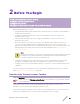
2 Before You Begin Download the ExtremeLocation Toolbox Configure ExtremeLocation Server Configure Proxy Server Simultaneous Calibration using 2.4 GHz and 5.0 GHz Bands Before starting calibration, you must: • • • • Download the ExtremeLocation Toolbox from Google Play Store™. The Toolbox is only available for Android version 7 and above. Configure the parameters required to connect to the ExtremeLocation server and to your ExtremeLocation account. Optional.
Before You Begin On successful installation, an icon is placed on your device's home screen. The ExtremeLocation Toolbox has the word WIFI Toolbox included in the icon. Use this to distinguish this app's icon from a similar icon for the ExtremeLocation Demo App. The ExtremeLocation Demo App has the word DEMO included in the icon. Select the ExtremeLocation Toolbox's icon from the device's main screen to launch the application. If this is the first time you are accessing the app, its login screen displays.
Before You Begin To configure the ExtremeLocation server settings: 1 From the login screen of the ExtremeLocation Toolbox app, use the screen. icon to launch the settings Figure 2: Toolbox Settings Screen Use the ExtremeLocation Settings section of the Settings screen to configure the parameters relating to accessing the ExtremeLocation server. Similarly, use the Proxy Settings section of the screen to configure proxy settings for accessing the ExtremeLocation server.
Before You Begin 4 Use the icon located at the top left of the screen or use the device's saving the changes made to the ExtremeLocation Toolbox settings. icon to exit without The changes made to the settings are reverted and you are taken back to the ExtremeLocation Toolbox Login screen.
Before You Begin 2 Provide the following information: Field Description Proxy Address Enter the IP address of your organization's proxy server in the Proxy Address field. Proxy Port Enter the port on which your proxy server can be accessed within your organization's network. Enter this port value in the Proxy Port field. 3 Select the SAVE button located at the bottom of the screen to save changes made to the ExtremeLocation Toolbox settings.
Before You Begin Pairing Secondary Device ExtremeLocation Toolbox enables you to use the 2.4 GHz and 5.0 GHz radios simultaneously for RTLS calibration. However, since a calibrating device can only connect on one radio band, you have to use two devices to simultaneously calibrate RTLS on both the radio bands. The ExtremeLocation Toolbox enables simultaneous calibration by pairing the main device (Primary Device) with another device (Secondary Device) running in the other radio band.
Before You Begin 2 On the primary device, select the PAIR button to start the pairing process. The following screen displays. On the secondary device, tap the Pair button to start the pairing process.
Before You Begin The following screen displays.
Before You Begin 3 On the primary device, select the START button to start the pairing process. The following screen displays. 4 Tap the SCAN BLUETOOTH DEVICES button to start scanning for the secondary device. Note We recommend that you search for and pair your devices afresh. ExtremeLocation Toolbox does not support adding an already paired device as a secondary device (when paired outside the ExtremeLocation Toolbox app). If your device's bluetooth radios is not ON, you are prompted to switch it on.
Before You Begin On successful completion of the bluetooth pairing, the following screen displays on the primary device. The following information is displayed in Bluetooth Details section of this screen.
Before You Begin Field Description Primary mac Displays the MAC address of this device, the primary device. Secondary mac Displays the MAC address of the paired device, the secondary device. Paired Device Displays the common name for the primary device. This includes the make and model number as reported by the primary device. The following information is displayed for the Wifi Details section of this screen.
3 Login To ExtremeLocation Toolbox Login to your ExtremeLocation account using the ExtremeLocation Toolbox login screen. Important To successfully login to your ExtremeLocation account, you must configure the ExtremeLocation server information. For more information, see Before You Begin on page 10. Figure 4: ExtremeLocation Toolbox Login Screen You must use your ExtremeLocation account credentials to login to the ExtremeLocation Toolbox.
Login To ExtremeLocation Toolbox 4 Select the I agree to Terms and Conditions option. Extreme Networks recommends that you review the Terms and Conditions of this service before you login to the ExtremeLocation service. You must select this option before you can access the ExtremeLocation service through the ExtremeLocation Toolbox. To view the terms and conditions of using the ExtremeLocation service, select the Terms and Conditions link.
4 Calibration for Zones and RTLS Calibration RTLS Calibration Zone Calibration Calibration The following calibrations can be performed using the ExtremeLocation Toolbox application. • • Zone Calibration RTLS Calibration RTLS Calibration Introduction Real Time Locationing System enables you to locate your clients accurately on the physical floor at your sites.
Calibration for Zones and RTLS ExtremeLocation server for processing. Post processing , a RTLS visualization map is displayed on your device. This information is then used to map your customers on the floor map for the site where locationing is configured. For more information, see RTLS Calibration on page 24 Zone Calibration Introduction The Zone Tracking feature enables you to detect devices, visitors, assets, and associates within a zone. A zone is an area covered by an AP or a sensor.
Calibration for Zones and RTLS Extreme Networks also recommends that if there is a major change in the floor plan of the floor, you recalibrate RTLS and Zones to ensure that these settings are current. You would also need to re-calibrate your RTLS and zones when you move your existing access points to a different location. It is assumed that you are logged into the ExtremeLocation Toolbox.
Calibration for Zones and RTLS 1 Select the RTLS Calibration icon from the home screen of the ExtremeLocation Toolbox app. The List Of Sites screen displays. 2 From the list of sites managed by your ExtremeLocation account, select the site for which you want to calibrate RTLS for. Tap the site you want to calibrate. The List Of Floors screen displays. The List of Floors screen lists the floors configured for the selected site.
Calibration for Zones and RTLS 3 From the list of floors, tap on the floor that you want to configure RTLS in. The Floor Map screen displays. The screen displays the floor map of the selected floor and overlays all the access points deployed on the floor. 4 Optional: Use the markers for this floor. drop-down list to view the previously configured RTLS configuration ExtremeLocation stores information about the last RTLS configuration markers for you to review when required.
Calibration for Zones and RTLS 5 Select the RTL Calibration button from the bottom of the screen. The following dialog displays. The dialog displays the steps that you need to perform for completing RTLS calibration.
Calibration for Zones and RTLS 6 Select the Start Calibration button to start the process of calibrating RTLS. The Draw Path screen displays. By default an empty screen is displayed. Before you can start RTLS calibration, we recommend that you decide the path that you will take while configuring. It is recommended that you create a path that will cover most of the areas that are covered by the access points deployed in your floor.
Calibration for Zones and RTLS 7 Start creating a path by tapping a location on the floor map. A blue dot indicates the place where your RTLS calibration path starts. 8 Tap to create the next point in your calibration path. A new point is created and a dashed line is created automatically joining the current point with the previously selected point.
Calibration for Zones and RTLS 9 Create your path by repeating the above step as many times as required till you complete your calibration path. Note It is not necessary to complete your calibration path at the point where you started creating the path. Choose a path that is suitable for your floor and deployment. At any time, use the button located to the bottom right of the screen to undo your calibration point placement.
Calibration for Zones and RTLS 10 Once you have completed creating the calibration path, tap the Next button located to the bottom of the screen. The following screen displays. Use this screen to review the RTLS calibration path that you have created. If you are not satisfied with the path that you have created, select the REDO button to create the path again. Your existing path is cleared and you start with a plain floor map.
Calibration for Zones and RTLS This message indicates the number of calibration points that ExtremeLocation Toolbox has inserted in the path that you have created. Tap the icon at the bottom of the message window. The following screen displays. The screen displays the locations of all the calibration points inserted by ExtremeLocation Toolbox. 12 Select the NEXT button to start the process of RTLS data collection. The following screen displays.
Calibration for Zones and RTLS • • Step Detection Calibration For Tap on Step Detection to select it. Use this field to indicate how data is collected at each calibration point identified by ExtremeLocation Toolbox. The following message is displayed. When you select Assisted Mode, ExtremeLocation Toolbox collects data at each calibration point automatically when you stop at the calibration point.
Calibration for Zones and RTLS If you have selected Assisted Mode, ExtremeLocation Toolbox automatically collects RTLS calibration data for the calibration point. In both modes, the following screen displays. Once the data is collected for the calibration point, the screen displays the following message. Select the Continue to Next Point button to move to the next calibration point in the path.
Calibration for Zones and RTLS Repeat this process till you have completed walking along the path that you have created and ExtremeLocation Toolbox has collected data at all calibration points in the path. The following message is displayed. 15 Select the OK button to complete RTLS calibration. RTLS Calibration Report To view the RTLS calibration report: 1 To view the RTLS calibration heat map, select the icon to the top right of the screen. A menu is displayed.
Calibration for Zones and RTLS Select the Calibration item to expand it.
Calibration for Zones and RTLS 2 Select the Visualization mode menu item. The Heat Map screen displays On the heat map, areas in GREEN indicate that enough data points were collected. However, areas in RED indicate that the collected data was insufficient for RTLS locationing. 3 To select a different band and view its heat map, select the drop-down located to the top right of the screen. The screen refreshes to display the heat map of the selected band.
Calibration for Zones and RTLS 2 Tap the Validation menu item. A list of sites configured for this ExtremeLocation account displays. 3 From this list, tap the site that you want to validate calibration for. A list of floors configured for the selected site displays. 4 From the list of floors for the site, select the floor that you want to validate the RTLS configuration for. An empty floor map of the selected floor is displayed.
Calibration for Zones and RTLS 6 Tap the Continue button located at the bottom of this screen. The ExtremeLocation Toolbox fetches the location as reported by the ExtremeLocation service and marks that location with the icon. This screen shows a message that displays the difference in accuracy between the actual location of the device and the system reported distance. Use the message to decide if the difference is acceptable. If not acceptable, perform the RTLS calibration again.
Calibration for Zones and RTLS 8 Use the DONE button, located to the top right of the screen, to complete the validation process. Zone Calibration Calibrating your zones is an important task to increase the accuracy of your ability to track your customers through your sites. When the zones are not calibrated properly, accurate zone tracking data is not received by ExtremeLocation. This prevents ExtremeLocation from placing the client within the correct zone.
Calibration for Zones and RTLS 1 Select the Zone Calibration icon from the home screen of the ExtremeLocation Toolbox app. The List Of Sites screen displays. 2 From the list of sites managed by your ExtremeLocation account, select the site for which you want to calibrate the zones. Tap the site you want to calibrate. The List Of Floors screen displays. The List of Floors screen lists the floors configured for the selected site.
Calibration for Zones and RTLS 3 From the list of floors, tap on the floor that you want to configure zones in. The Floor Map screen displays. The screen displays the floor map of the selected floor and overlays all the access points deployed on the floor. 4 Optional: Tap the 1 Client Added control to load a screen that displays a list of clients added by this calibration app. The Device List screen displays a list of client devices that have been added for use with the Zone Calibration activity.
Calibration for Zones and RTLS The selected device is immediately removed from the list of devices that can be used for zone calibration. You can also use this screen to add an additional four (4) devices (total of five (5) inclusive of the current device) to use for zone calibration. To add additional devices to this list, use the + button to the top right of the screen. The following dialog appears. Provide a name for this device in the device name field.
Calibration for Zones and RTLS 5 Tap the Start Calibration button and immediately tap the icon of the access point that you want to calibrate the zone for. 6 To start the calibration, select the START button. The Zone Calibration process starts immediately and the following screen displays.
Calibration for Zones and RTLS The calibration process runs for three (3) minutes and records the signal strength of the client as reported by all the access points near the access point being calibrated. Signal strength data for the clients is captured every second from all the access points.
Calibration for Zones and RTLS At anytime, use the Stop Calibration button located to the bottom of the screen to stop zone calibration. At the end of the calibration the following message displays.
Calibration for Zones and RTLS 7 Optional: If you want to calibrate another access point, select the CHANGE AP button. 8 To stop calibration, select the NO button. This ends the calibration immediately. Use the YES button to indicate that you want to re-calibrate this access point again. Choose this option if you are not satisfied with this zone calibration for any reason. Calibration Report Zone calibration results are available for each floor of each site where this calibration was run.
Calibration for Zones and RTLS 1 Select the Calibration Reports button. The Calibration data screen displays. 2 Tap the Select AP Zone control's arrow to expand it. The field expands to display a list of the MAC addresses of all access points configured for this floor. 3 From the Select AP Zone drop down, tap the MAC address of the access point for which you want to view the calibration data. The following screen displays.
Calibration for Zones and RTLS The screen displays a widget for each access point near the access point being calibrated. Use the icon to expand the widget to fill the current view window. Use the same button to restore the widget to its previous size and location. Each graph widget displays a plot of the Min, Max and Median values of the RSSI for each device as identified by an access point listed by its MAC address. The bar graph displays the range of RSSI values detected by the access point.
A RF Domain Configuration Note These configurations are done using the WiNG user interface. For ExtremeLocation to work, the RF Domain policy's sensor configuration must point to an existing Sensor policy or to a newly created Sensor Policy. See Sensor Policy Configuration on page 56 for more information on creating a Sensor policy. To set the RF Domain's Sensor configuration: 1 Select Configuration > RF Domains > . The RF Domain screen displays.
RF Domain Configuration 2 Select Sensor from the menu on the left. The Sensor screen displays.
RF Domain Configuration 3 Select + Add Row from within the ExtremeLocation Appliance Configuration list. This adds a new row in the ExtremeLocation Appliance Configuration table. Only one row can be configured for this table. Provide the following information: Field Description Server Id Use the spinner control to assign a numeric ID for the ExtremeLocation server. The default ID value is 1. IP Address/Hostname Provide the host name of the ExtremeLocation server.
RF Domain Configuration 4 In the ExtremeLocation web user interface, locate your tenant account number. This number is located next to the icon at the top right of your screen. 5 Specify your ExtremeLocation Tenant Account Number in the Tenant Account field . 6 Select OK to save the changes to the RF Domain Sensor configuration, or select Reset to revert to the last saved configuration.
RF Domain Configuration 7 Select Basic from the RF Domain menu on the left. The RF Domain basic configuration screen appears. Figure 5: RF Domain Basic Configuration Screen 8 Select the Country drop-down to expand it and select the country of operation for this access point. 9 Select OK to save the changes to the RF Domain Basic configuration, or select Reset to revert to the last saved configuration. 10 Select Exit to exit the RF Domain configuration screen.
B Sensor Policy Configuration Note These configurations are done using the WiNG user interface. The access point radio can function as a sensor and upload information to the ExtremeLocation server. When an access point radio functions as a sensor, it is, in the sensor mode, able to scan across all legal channels within the 2.4 and 5.0 GHz bands. The access point works in conjunction with the ExtremeLocation server to provide locationing service.
Sensor Policy Configuration 2 Select Add to define a new sensor policy. The following screen appears. Figure 7: Add new Sensor Policy Screen 3 Provide a name in the Name field. Sensor policy name cannot exceed 32 characters and cannot contain space. 4 Select Continue to create the Sensor policy. 5 Select Exit to exit this screen without creating a new sensor policy. The Sensor Policy addition screen displays with the Scan Mode set to Default-Scan.
Sensor Policy Configuration 7 Select the Scan Mode setting appropriate to your requirement. Note Scan Mode should be set to determine the channel list for dedicated sensors. It is recommended that the Channel List should be limited to the operating channels of the deployment. For the 5.0GHz band, it is recommended that the DFS channels not be included in Channel Scan list. Client devices are prohibited from actively probing on these DFS channels.
C RF Domain - Sensor Policy Configuration Note These configurations are done using the WiNG user interface. For ExtremeLocation to work, the RF Domain policy must have a Sensor Policy applied to it. See Sensor Policy Configuration on page 56 for more information on creating a Sensor policy. To set the RF Domain's Sensor Policy configuration: 1 Select Configuration > RF Domains > . The RF Domain screen displays.
RF Domain - Sensor Policy Configuration 2 Select Sensor from the menu on the left. The Sensor screen displays.
RF Domain - Sensor Policy Configuration 3 From the Sensor Policy field, select the appropriate sensor policy. 4 Select OK to save the changes to the RF Domain Sensor configuration, or select Reset to revert to the last saved configuration. 5 Select Exit to exit the RF Domain configuration screen. 6 From the top right corner of the screen select the Commit and Save button to commit and save changes to the RF Domain.