
Specifications


66 ExtremeWare XOS 10.1 Concepts Guide
Virtual LANs (VLANs)
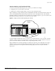
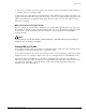
Figure 4: Physical diagram of tagged and untagged traffic
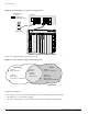
Figure 5 is a logical diagram of the same network.
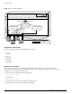
Figure 5: Logical diagram of tagged and untagged traffic
In Figure 4 and Figure 5:
• The trunk port on each switch carries traffic for both VLAN Marketing and VLAN Sales.
• The trunk port on each switch is tagged.
• The server connected to port 25 on system 1 has a NIC that supports 802.1Q tagging.
EX_064
System 1
= Marketing
= Sales
M
S
= Tagged port
Marketing & Sales
M
S
MS
SS
M
M
M
M
S
S
S
S
MM
SS
SS
802.1Q
Tagged server
System 2
EW_025
*Tagged Ports
Sales
System 1
Port 25 *
Port 29 *
System 2
Slot 1, Port 1 *
Marketing
System 1
Ports 1-4 & 9-12
System 2
Slot 1, Port 2
Slot 2, Ports 1-8 & 17-24
System 1
Ports 5-8, 13-16 & 32
System 2
Slot 1, Port 3
Slot 1, Port 4
Slot 2, Ports 9-16 & 25-32