Px Series Application Switch Installation and Configuration Guide Extreme Networks, Inc. 3585 Monroe Street Santa Clara, California 95051 (888) 257-3000 http://www.extremenetworks.com Published: April 2002 Part number: 100101-00 Rev.
©2002 Extreme Networks, Inc. All rights reserved. Extreme Networks and BlackDiamond are registered trademarks of Extreme Networks, Inc. in the United States and certain other jurisdictions.
Contents Preface Introduction 1-vii Conventions 1-viii Related Publications 1 2 1-ix Server Load Balancing Concepts Purpose of Server Load Balancing Terms 1-1 1-2 Load Balancing Modes Layer 4 Load Balancing Layer 7 Load Balancing and Content Analysis 1-3 1-3 1-4 Port Rewrite 1-6 Getting Started on Load Balancing Configuration 1-6 Installing the SummitPx1 Application Switch Overview of the SummitPx1 Application Switch SummitPx1 Front View SummitPx1 Application Switch Rear View 2-1 2-1 2-3
Free-Standing 3 4 iv 2-5 Powering On the SummitPx1 2-5 Setting Up Console Communication Configuring Switch IP Parameters Configuring the 10/100 Ethernet Management Port 2-6 2-7 2-8 Installing the PxM Application Switch Module Installing I/O Modules 3-1 Removing I/O Modules 3-2 Managing the Switch Using the Command-Line Interface Abbreviated Syntax and Command Completion Syntax Symbols Line-Editing Keys Specifying Text Values Command History Prompt Text 4-2 4-2 4-2 4-3 4-3 4-4 4-4 Configuring
Configuring a Startup Banner Message Starting the GlobalPx Content Director Agent Example Configuration 5 6 4-18 Configuring Servers and Services Configuring Real Servers 5-1 Configuring Server Groups 5-2 Configuring Virtual Services Layer 4 Port-based Load Balancing Layer 7 Virtual Services Configuring Traffic Tagging 5-3 5-4 5-4 5-5 Configuration Example 5-6 Choosing Policies, Persistence Modes, and NAT Scheduling Policies 7 4-17 4-17 6-1 Persistence Modes UDP Flow Persistence Client IP Pe
Configuration Example 8 9 10 7-9 Configuring Redundancy Using VRRP with the SummitPx1 Adding and Configuring VRRPs Using VRRP in Existing Redundant Networks VRRP Automatic Synchronization 8-1 8-2 8-3 8-4 Configuring Redundancy for the PxM Using ESRP with the PxM Configuring the PxM for Multiple VLANs 8-6 8-6 8-7 Configuring a Default Gateway 8-8 Health Checks Overview Server Startup Pacing 9-1 9-2 Health Checking Procedure 9-3 Configuring Health Checks Types of Health Checks Timers and Counte
Preface This preface provides an overview of this guide, describes guide conventions, and lists other publications that may be useful. Introduction This guide provides the required information to configure the Extreme Networks Px series application switches, SummitPx1TM and PxMTM. This guide is intended for use by network administrators who are responsible for installing and setting up network equipment.
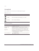
Preface Conventions Table 1 and Table 2 list conventions that are used throughout this guide. Table 1: Notice Icons Icon Notice Type Alerts you to... Note Important features or instructions. Caution Risk of personal injury, system damage, or loss of data. Warning Risk of severe personal injury. Table 2: Text Conventions Convention Description Screen displays This typeface indicates command syntax, or represents information as it appears on the screen.
Related Publications Related Publications The publications related to this one are: • ExtremeWare Software User Guide • Px Series Application Switch Release Notes Documentation for Extreme products is available on the World Wide Web at the following location: • http://www.extremenetworks.
Preface x Px Series Application Switch Installation and Configuration Guide
1 Server Load Balancing Concepts The Px series application switch marks the next step in server load balancing. Using a revolutionary hardware design, the Px series application switch is designed to help website administrators achieve levels of availability and scalability never before possible.
The Px series application switch can examine actual user requests, rather than simply forwarding the requests to the servers.
Load Balancing Modes In this document, the Internet users are referred to as clients, because they are clients of the application switch. The website, which is actually an address inside the application switch, is also called a virtual IP address, or VIP. Because the Px series application switch uses the unique combination of IP address and source port, the VIP is referred to as a virtual service.
Client Real Server SYN 1 SYN/ACK ACK DATA (http request) WS_013 Figure 1-2: Single client-server transaction using layer 4 As soon as the first request from the client is received at the application switch, the application switch uses the server-selection policy configured for the VIP to select the server and immediately sends out the NAT-ed request to the real server. The client and server continue the connection establishment protocol using the application switch in the middle, NAT-ing the traffic.
Load Balancing Modes chosen to process the request, using a source IP address that is part of a proxy pool inside the application switch. After a connection is established between the application switch and the real server, the application switch forwards the buffered data to the server. The server sends any response to the application switch.
Port Rewrite When a request is sent by a client to a VIP service, the request contains the well-known port number for the requested application. For example, the well-known port number for HTTP is port 80. You can configure the application switch to rewrite the port, configuring a server group to use a specific port, other than the well-known port number for the application.
Getting Started on Load Balancing Configuration a Configure the real servers that will be load balanced. b Create groups of servers, and put the real servers into them. c Create a virtual service. — If the virtual service is layer 4, assign a server group to it. — If the virtual service is layer 7, create the appropriate domains and pattern-rules, and assign server groups to the pattern-rules. For more information, see Chapter 5.
1-8 Px Series Application Switch Installation and Configuration Guide
2 Installing the SummitPx1 Application Switch This chapter describes how to install the SummitPx1 configuration of the Px series application switch.
Table 2-1 describes the LED behavior on the SummitPx1. Table 2-1: Px series application switch LEDs LED Color Indicates Link Green The 1000Base-T link is operational. Yellow flashing There is activity on this link. Management Power Green flashing ■ Slow The Px series application switch is operating normally. ■ Fast Power On Self Test (POST) in progress. Red The Px series application switch has failed its POST. Green The Px series application switch is powered up.
Overview of the SummitPx1 Application Switch Table 2-2: DB-9 Adapter Pinouts TO: DB-9 FROM: RJ45 SHELL Signal Description Pin 6 Pin 1 DSR Pin 8 Pin 2 CTS Pin 2 Pin 3 RD Pin 5 Pin 4 SG NC Pin 5 -- Pin 3 Pin 6 TD Pin 7 Pin 7 RTS Pin 4 Pin 8 DTR For more information on connecting and configuring these ports, see “Setting Up Console Communication” on page 2-6. SummitPx1 Application Switch Rear View Figure 2-2 shows the SummitPx1 application switch rear view.
Determining the Location The SummitPx1 is suited for use in the office, where it can be free-standing or mounted in a standard 19-inch equipment rack. Alternatively, the device can be rack-mounted in a wiring closet or equipment room. Two mounting brackets are supplied with the device. When deciding where to install the SummitPx1, ensure that: • The unit is accessible and cables can be connected easily. • Water or moisture cannot enter the case of the unit.
Powering On the SummitPx1 WS_011 Figure 2-3: Fitting the mounting bracket 5 Repeat steps 2-4 for the other side of the device. 6 Insert the application switch into the 19-inch rack. Ensure that ventilation holes are not obstructed. 7 Secure the device with suitable screws (not provided). 8 Connect cables. Free-Standing The SummitPx1 application switch is supplied with four self-adhesive rubber pads. Apply the pads to the underside of the device by sticking a pad at each corner of the device.
If the application switch passes the POST, the MGMT LED blinks at a slow rate (1 blink per second). If the application switch fails the POST, the MGMT LED shows a solid yellow light. Setting Up Console Communication To manage the application switch locally, you must connect to the management console to configure the switch’s Ethernet management port using a serial connection. This section describes how to to configure the SummitPx1 for communication with the console interface.
Setting Up Console Communication cable with which to connect most PCs to this port. The console port settings are as follows: Baud rate 9600 Data bits 8 Stop bit 1 Parity None Flow control None Each interface has a unique IP address. Before you can start a Telnet session, you must set up the IP parameters of the port you will use for management, as described in the following sections. To open the Telnet session, you specify the IP address of the port.
Writing data to Flash Done 4 When you are finished using the facility, log out of the application switch. You can now access the Gigabit Ethernet port directly via Telnet. Configuring the 10/100 Ethernet Management Port The 10/100BT Ethernet management port provides dedicated remote access to the application switch using TCP/IP. It supports Telnet using the command-line interface. The 10/100BT port is designed to be used as an out-of-band management port only.
3 Installing the PxM Application Switch Module The PxM configuration of the Px series application switch is a BlackDiamond module. The configuration information and specifications for the BlackDiamond I/O modules are described in detail in the Extreme Networks Consolidated Hardware Guide, as well as the module installation and removal procedures. For convenience, the information on installing and removing modules is repeated here.
Caution: You can install I/O modules only in slots 1 through 16 in the BlackDiamond 6816 or slots 1 through 8 in the BlackDiamond 6808. I/O modules do not fit in slots A, B, C, or D. Forceful insertion can damage the I/O module. 2 Attach the ESD strap that is provided to your wrist and connect the metal end to the ground receptacle that is located on the top-left corner of the switch front panel.
Removing I/O Modules 3 Simultaneously rotate the ejector/injector handles outward to disengage the module from the backplane. 4 Slide the module out of the chassis. 5 If you are not going to install a replacement I/O module, cover the slot with a blank faceplate. Otherwise, follow the I/O module installation procedure above. 6 Repeat this procedure for additional modules, if applicable.
3-4 Px Series Application Switch Installation and Configuration Guide
4 Managing the Switch This chapter covers the following topics: • Using the Command-Line Interface page 4-2 • Configuring Management Access on page 4-4 • Managing the PxM on page 4-7 • Configuring VLANs on page 4-8 • Configuring SNMP on page 4-9 • Configuring DNS Client Services on page 4-10 • Utilities on page 4-15 • Example Configuration on page 4-18 Px Series Application Switch Installation and Configuration Guide 4-1
Using the Command-Line Interface To use the command-line interface: 1 Enter the command name. You can use abbreviated syntax; see below. 2 If the command includes a parameter, enter the parameter name and value. The value specifies how you want the parameter to be set. Values can be numbers, strings, or addresses, depending on the parameter. 3 After entering the complete command, press [Return]. Most commands are not executed immediately, but are deferred until you issue the build command.
Using the Command-Line Interface Table 4-1: Command Syntax Symbols (continued) Symbol Description vertical bar | Separates mutually exclusive items in a list, one of which must be entered. Do not type the vertical bar. braces { } Enclose an optional value or a list of optional arguments. One or more values or arguments can be specified. Do not type the braces. Line-Editing Keys Table 4-2 describes the line-editing keys available when using the command-line interface.
value. You must use quotes if the text value includes any non-alphanumeric characters, such as spaces, dashes, or dots. Command History The Px series application switch keeps a history of the last 49 commands you entered. To display a list of the most recent commands, enter: history Prompt Text The prompt text is taken from the SNMP sysname setting. For more information, see ”Configuring SNMP” on page 4-9. The number that follows the colon indicates the sequential line/command number.
Configuring Management Access • Administrator An administrator-level account can view and change all switch parameters. It can also add and delete users, and change the password associated with any account name. The administrator can disconnect a management session that has been established by way of a Telnet connection. If this happens, the user logged on by way of the Telnet connection is notified that the session has been terminated.
Creating Accounts The application switch can have a total of 16 management accounts. You can use the default accounts (admin and user), or you can create additional accounts with new names and passwords. To create a new account, follow these steps: 1 Log in to the switch as admin. 2 At the password prompt, press [Return], or enter the password that you have configured for the admin account.
Managing the PxM Managing the PxM You can manage the PxM in any of the following ways: • Using the connect command in the BlackDiamond. • Using the serial port (useful for debugging). • Using the 101100 port (for out-of-band management). VLANs are always enabled on the PxM. A configuration that does not contain VLAN information will fail to build and report syntax errors for the PxM. You must configure a VLAN on the MSM before you configure it on the PxM. See “Configuring VLANs” on page 4-8.
Some commands do not work at all if the PxM is not booted and ready. It can take more than two minutes to boot. To verify from the MSM that a PxM is booted, use the command show pxm. • If the PxM is booted and ready, the card state is displayed as operational. • If the PxM for a slot has not been booted or is not ready, the command shows no status for that slot. Configuring VLANs The Px series application switch supports up to 4,096 VLANs.
Configuring SNMP To assign a VLAN tag to a service, use the following command: config service vip vlan port protocol [tcp|udp] [L4|L7] server-group-name
Table 4-4: SNMP Configuration Settings Setting Description Community strings The community strings allow a simple method of authentication between the application switch and the remote Network Manager. There are two types of community strings on the application switch. ■ ■ Read community strings provide read-only access to the application switch. The default read-only community string is public. Read-write community strings provide read and write access to the application switch.
Using Secure Shell 2 (SSH2) In addition, the nslookup utility can be used to return the IP address of a hostname. Table 4-5 lists commands used to configure the DNS client. Table 4-5: DNS Client Configuration Commands Command Description config dns-client add Adds a DNS name server(s) to the available server list for the DNS client. Up to three name servers can be configured.
The ExtremeWare SSH2 switch application also works with SSH2 client and server (version 2.x or later) from SSH Communication Security, and the free SSH2 and SCP2 implementation (version 2.5 or later) from OpenSSH. The SFTP file transfer protocol is required for file transfer using SCP2. Enabling SSH2 for Inbound Switch Access Because SSH2 is currently under U.S.
Using Secure Shell 2 (SSH2) You are prompted to enter information to be used in generating the key. The key generation process takes approximately ten minutes. Once the key has been generated, you should save your configuration to preserve the key. To use a key that has been previously created, use the following command: config ssh2 key pregenerated You are prompted to enter the pregenerated key. The key generation process generates the SSH2 private host key.
For example, to copy an image file saved as image1.xtr to switch with IP address 10.10.0.5 as the primary image using SCP2, you would enter the following command within your SSH2 session: scp image1.xtr admin@10.20.0.5:primary.img To copy the configuration from the switch and save it in file config1.save using SCP, you would enter the following command within your SSH2 session: scp admin@10.10.0.5:configuration.cfg config1.save SSH2 Client Functions on the Switch In ExtremeWare version 6.2.
Utilities Utilities The Px series application switch offers utilities for the following operations: • Checking Basic Connectivity on page 4-15 • Logging on page 4-16 • Configuring a Startup Banner Message on page 4-17 • Starting the GlobalPx Content Director Agent on page 4-17 Showing CPU Load Use the following command to show the CPU load: top This is similar to the UNIX top command. The idle task, BGTask, shows 99%-100% if nothing else is going on.
Logging The Px series application switch supports two logging facilities, a local log and the UNIX syslog facility for remote logging. The application switch log tracks all configuration and fault information pertaining to the device. The switch maintains 1,000 messages in its internal log. To enable the log, use the command: enable log To view the log, use the command: show log The argument is optional. By default, all messages are shown.
Utilities Configuring a Startup Banner Message To configure a banner message to display after reboot, use the following command: config banner At the prompt, type the banner message. To exit the banner input script, type [Return][Return].
To start and stop the GlobalPx Content Director agent on the Px series application switch, use the following commands: enable gslb-agent [port ] disable gslb-agent To check on the agent’s activities, use the following command: show gslb-agent gslb-agent is [enabled | disabled] listening on IP address a.b.c.
Example Configuration The following commands configure all system-related facilities: #---------------------------------------------------------------# system configuration #---------------------------------------------------------------config system-ip 64.1.1.10 / 24 config default-gateway 64.1.1.1 disable vlan config mgmt ipaddress 10.10.10.10 / 24 enable syslog config syslog ip 10.10.10.
4-20 Px Series Application Switch Installation and Configuration Guide
5 Configuring Servers and Services This chapter describes how to configure the real servers that will be load balanced, how to create groups of servers and put the real servers into them, and how to create a layer 4 or layer 7 virtual service.
answer requests. Servers can share an IP address, but the port must be unique for each server. • Max-connections represents the maximum number of concurrent connections this server can handle. After that number is reached, no more connections are sent to that particular server until some of the open ones have been closed (unless a persistence method is specified; see “Persistence Modes” on page 6-2). Most servers can handle fewer than 5,000 connections.
Configuring Virtual Services a system in another geographical location).
You can assign a specific VLAN tag to a virtual service. VLAN tags for services are optional for the SummitPx1, but required on the PxM. To assign a VLAN tag to a service, use the following command: config service vip vlan port protocol [tcp|udp] [L4|L7] server-group-name
Configuring Virtual Services config pattern-rule “” server-group-name Pattern rules specify the URL that is being matched and the server group that should be used to forward traffic for that URL match. config domain default config pattern-rule default server-group-name All layer 7 service definitions require at least a default pattern rule, to define the “last resort” rule for URL switching. If you use any domain other than domain*, you must define a default domain.
. Table 5-1: Tag Specifications Tag Specification Description Tag Range dot1p-to-svr Applies the specified tag to the 802.1p header for packets directed to the server. 0-7 dot1p-to-net Applies the specified tag to the 802.1p header for packets directed to the network. 0-7 diffserv-to-svr Applies the specified tag to the DiffServ code point for packets directed to the server.
Configuration Example #---------------------------------------------------------------# servers #---------------------------------------------------------------config server index 1 ip 64.1.1.50 port 80 max-con 5000 weight 1 config server index 2 ip 64.1.1.51 port 80 max-con 5000 weight 1 config server index 3 ip 64.1.1.
5-8 Px Series Application Switch Installation and Configuration Guide
6 Choosing Policies, Persistence Modes, and NAT This chapter describes how to specify scheduling polices for layer 4 load balancing, session persistence, and network address translations.
The Px series application switch supports the following scheduling policies: Table 6-1: Scheduling Policies Specifier Policy rr round robin Description Distributes clients evenly across the web server group by passing each new connection request to the next server in line. The first client connection is sent to the first server, the second to the second server, and so on, until each server has a connection.
Persistence Modes accesses the website, it opens a session with one of the web servers. To optimize the communication and, in many cases, for the website to function correctly, each time the client communicates with the website within the current session, the client must communicate with the web server that established the session.
Server 1 145.12.1.1 Client 64.1.1.7 www.buystuff.com Server 2 Server 3 WS_001 Figure 6-1: Client IP persistence mode The following transactions occur in Figure 6-1: • The client with IP address 145.12.1.1 transmits its first TCP request to www.buystuff.com at its VIP address, 64.1.1.7. • Using its configured load balancing policy, the Px series application switch selects server 3 as the web server. • The application switch sends the first request to the selected web server.
Persistence Modes Configuring Client IP Stickiness To enable and disable client IP persistence (stickiness), use the following commands: [enable | disable] sticky [L4 | L7] client-ip Client IP entries are aged out of the database in a configurable amount of time. By default, they are deleted after 30 seconds without use. To adjust these timers, use the following command: config sticky client-ip timeout HH:MM:SS The timer affects both layer 4 and layer 7.
Server 1 10.1.1.1 64.1.1.7 A www.buystuff.com B C E Client F D F Server 2 10.1.1.2 E Cookie: serverip=10.1.1.3 Server 3 10.1.1.3 WS_002 Figure 6-2: Self-identifying cookie persistence mode The following transactions occur in Figure 6-2: • The website administrator of www.buystuff.com sets up each web server (server 1, server 2, and server 3) to create a cookie that contains the real IP address of the web server. — Cookies created by server 1 contain IP address 10.1.1.1.
Persistence Modes • Using its configured load balancing policy, the Px series application switch selects one of the web servers. In this example, server 3. • A three-way TCP handshake is established between the Px series application switch (C) and server 3 (D). • The application switch forwards the first data request from the client to server 3 (E). • The first response from server 3 to the client contains a cookie. (F). The cookie contains the real IP address of the server, 10.1.1.3.
# Additional information may be useful during debugging print start_html('Cookie Tester'); if (!$ExistingHostCookie) { print "No cookie named $SLBCookie existed
\n"; print "It was set to the local host address of $HostIPAddr
\n"; } elsif ($ExistingHostCookie ne $HostIPAddr) { print "The cookie named $SLBCookie was set for host $ExistingHostCookie
\n"; print "It was reset to the local host address of $HostIPAddr
\n"; } else { print "The cookie named $SLBCookie was correctly set to $ExistingHostCo
Persistence Modes user=samsmith96754 D A B F E 64.1.1.7 Server 1 rs ive ie l De ook c www.mybank.com C Database E Server 2 ss se G ta G Da Client n io Sam Smith Server 3 WS_003 Figure 6-3: Hashed cookie persistence mode Figure 6-3 shows a typical financial website named www.mybank.com. This website has three real servers, each connected to a single backend database system.
• The client transmits its first TCP request (A) to www.mybank.com at its publicly-known VIP address, 64.1.1.7. • The Px series application switch responds (B) on behalf of 64.1.1.7, and the three-way TCP handshake is established between the client and the Px series application switch. • Using its configured load balancing policy, the Px series application switch selects one of the web servers. In this example, server 1.
Persistence Modes Unlike self-identifying cookie persistence and hashed cookie persistence, learned cookie persistence does not require the website administrator to make any changes to the website. Learned cookie persistence is a best-effort persistence mode that creates a short-term stickiness between the client and the web server. Figure 6-4 illustrates learned cookie persistence mode. Server 1 10.1.1.1 64.1.1.7 A www.buystuff.com B C E Client 65.11.11.11 F D F Server 2 10.1.1.
• A three-way TCP handshake is established between the Px series application switch and server 3. • The application switch makes the following entry in its database: Cookie Source IP Address Destination VIP Address Real Server IP Address 65.11.11.11 64.1.1.7 10.1.1.3 • The application switch forwards the first data request from the client to server 3 (E). • Server 3 sends a cookie to the client (via the application switch) (F).
Persistence Modes is being done, a default domain and pattern rule are still needed. The commands are as follows: config domain default config pattern-rule default server-group-name cookie-name cookie-type [self | hash | learned] Because learned cookie mode uses a database to track users, there is a configurable timer. If a database entry has not been used for the amount of time specified by the timer, the database entry is deleted.
NAT Modes Network address translation (NAT) is one of the cornerstones of server load balancing. To balance the load between the various real servers, the server load balancer uses a single IP address, called a virtual IP address, to represent the entire group of servers that make up a website. When a client request arrives at the virtual IP address, the load balancer must rewrite the destination IP address, so that it can forward the request to a server for processing.
NAT Modes Configuring Full-NAT Mode and Proxy IP Addresses Full-NAT mode is the default behavior of the application switch. If another NAT mode was in use previously, use the following command to set it back to full: config nat-mode full To function properly, the application switch requires that proxy IP addresses be configured. These proxy addresses are used as the source IP addresses for the outbound connection to the server.
that of the real server, and that the TCP source port for the request is the same as the port of the network service that is being load balanced. If a request meets these criteria, it should be sent to the application switch as its next hop. Advantages of Half-NAT mode are: • Allows the server logs on the real website to reflect the IP address of the real client making a request, rather than a proxy address of the application switch.
Configuration Example When you configure half-NAT mode, you can also configure gateway mode for the application switch. Gateway mode specifies an IP address that a server’s default gateway can forward to, as if the application switch were another router. The application switch can then switch the forwarded traffic to another router, even one on another VLAN.
Real servers SummitPx1 Syslog server Net manager 10.10.10.20 10.10.10.21 system IP 64.1.1.10 proxy IP 64.1.1.11-24 Management net 10.10.10.1 64.1.1.50 64.1.1.51 Management IP 64.1.1.10 VIP 64.1.2.10 Layer 3 switch 64.1.1.1 DNS server 64.1.1.52 SSL servers 64.1.1.60 Internet 64.1.1.9 64.1.1.
Configuration Example config pattern-rule “default” server-group-name yourdomain cookie-name “session-id” cookie-type learn config service vip 64.1.2.11 port 443 protocol tcp l7 class https config domain name default config pattern-rule “default” server-group-name ecom #---------------------------------------------------------------# system configuration #---------------------------------------------------------------config system-ip 64.1.1.10 / 24 config default-gateway 64.1.1.
6-20 Px Series Application Switch Installation and Configuration Guide
7 URL Switching This chapter describes how the Px series application switch performs level 7 load balancing, directing client requests to server groups by acting as a proxy and looking inside each request, using domain or URL switching.
Server Group 1 Outside network Server Group 2 Server Group 3 WS_005 Figure 7-1: Typical switching scenario Domain Switching Domain switching uses the requested domain name to select the appropriate server group. For example, in Figure 7-2, there are three server groups: • www.buystuff.com • www.speakyourmind.net • www.buythisnow.
Domain and URL Switching Server Group 1 www.buystuff.com www.speakyourmind.net 192.1.1.1:80 Client Server Group 2 www.speakyourmind.net Server Group 3 www.buythisnow.net WS_006 Figure 7-2: Domain switching example The Px series application switch uses a single VIP, located at 192.1.1.1:80, to service all three domains. When the client request arrives, the application switch examines the request to determine the domain name being requested. In Figure 7-2, the domain name requested is www.speakyourmind.
config config config config config config config config config config config config config config domain name buystuff.com pattern-rule default server-group-name domain name www.buystuff.com pattern-rule default server-group-name domain name speakyourmind.com pattern-rule default server-group-name domain name www.speakyourmind.com pattern-rule default server-group-name domain name buythisnow.com pattern-rule default server-group-name domain name www.buythisnow.
Configuring URL Switching www.buystuff.com Server Group 1 default Request 1: www.buystuff.com Client Request 2: www.buystuff.com/dvds Server Group 2 /stereos Server Group 3 /dvds WS_007 Figure 7-3: Simple URL switching example By directing each of these unique types of requests to a different pool of servers at the application switch, you have the flexibility to move these resources without changing dozens of links. You can also split out different sections of your website virtually on-the-fly.
www.buystuff.com Server Group 1 /ebooks/ ISBNxxxxxxxx Client Server Group 2 /ebooks/ ISBNxxxxxxxy WS_008 Figure 7-4: More Complicated URL switching example In Figure 7-4, buystuff.com decides to start selling electronic books online and they need to store an entire publisher’s catalog on the site. Terabytes of storage are needed, along with a flexible way of addressing all of the information. By using URL switching, a highly scalable approach can be used.
Configuring URL Switching www.buystuff.com Server Group 1 /ebooks/authorsa/* Server Group 2 Client /ebooks/authorsb/* Server Group 3 /ebooks/authorsc/* .. . Server Group 26 /ebooks/authorsz/* WS_009 Figure 7-5: Hierarchical approach to pattern rules In Figure 7-5, the pattern rules direct user requests as follows: • www.buystuff.com/ebooks/authorsa/* are directed to server group 1 • www.buystuff.com/ebooks/authorsb/* are directed to server group 2 • www.buystuff.
config config config config config config config config config config config config domain name www.ebooks.com pattern-rule “authorsa” server-group-name authorsa pattern-rule “authorsb” server-group-name authorsb pattern-rule “authorsc” server-group-name authorsc pattern-rule default server-group-name mainpage domain name ebooks.
Configuration Example The wildcard (*) in the second line refers any request with an unspecified domain name (any request in which the domain name is not present in the HTTP header) to the default server group sg2. The application switch reads the HTTP header to determine the domain name format. You cannot configure HTTPS in this way because the header is encrypted and not visible to the application switch.
SummitPx1 Syslog server Net manager 10.10.10.20 10.10.10.21 system IP 64.1.1.10 proxy IP 64.1.1.11-24 Management net Application servers 64.1.1.50 10.10.10.1 Management IP 64.1.1.10 VIP 64.1.2.10 Internet Layer 3 switch 64.1.1.1 Streaming media 64.1.1.80 64.1.1.51 64.1.1.60 64.1.1.61 64.1.1.70 64.1.1.
Configuration Example config server-group name images policy rr config server-group name images add-server index 10 - 11 config server-group name media policy rr config server-group name media add-server index 20 # # #---------------------------------------------------------------# service-table #---------------------------------------------------------------config service vip 64.1.2.10 port 80 protocol tcp l7 class http config pattern-rule “*.gif” server-group-name images config pattern-rule “*.
config config config config config config 7-12 snmp sysName “balancer” snmp sysLocation “Exodus Colo” snmp sysContact “Web Admin” add trap receiver 10.10.10.
8 Configuring Redundancy This chapter describes how to configure redundancy for the Px series application switch. For the SummitPx1, you use the industry standard VRRP. For the PxM, you use the Extreme Standby Router Protocol (ESRP).
The only difference between a traditional VRRP implementation and the Px series application switch implementation is that instead of using the VRRP MAC address for a single layer 3 router address, the Px series application switch uses the VRRP MAC address for all VIPs configured in the system. Whenever the VRRP state changes, all VIPs either start accepting traffic and making forwarding decisions, or stop doing so. For VRRP to work, there must be a layer 2 adjacency between the application switches.
Using VRRP with the SummitPx1 config vrrp add vrid config vrrp vrid priority 100 enable vrrp build To set VRRP to preempt whenever it has a higher priority than the active system, or to prevent it from preempting, use this command: config vrrp vrid preempt|dont-preempt You can also set the frequency of advertisement intervals, using this command: config vrrp vrid advertisement-interval Using VRRP in Existing Redundant Networks The VRRP implementati
Internet / WAN or large Enterprise core Connections to ESRP ports configured for "host attach" Standby Px1 Active Px1 SummitPx1 configured with application aware VRRP Aggregation / Routing ESRP active ESRP standby Server racks Server Server Server Server Server Server Server Server Server Server Server Server WS_019 Figure 8-1: Application switch using multiple VLANs. For more information on configuring ESRP, see the ExtremeWare Software User Guide.
Using VRRP with the SummitPx1 on the backup. After all the commands have been replaced, the configuration is saved and the box rebooted. • Sends individual configuration commands from the master to the backup, where they are stored in local memory until a build command is issued on the master. The backup then executes the stored commands in sequence and issues its own build. The backup does not save the result. If you do not save it before the next boot, the configuration is lost.
Configuring Redundancy for the PxM You must use the the Extreme Standby Router Protocol (ESRP) to configure redundancy for the PxM. See “Using ESRP with the PxM” below. If you have multiple VLANs for the PxM, you must designate one VLAN as a master, and make all other VLANs domain members of the master VLAN. You can then configure ESRP for the master VLAN. See “Configuring the PxM for Multiple VLANs” on page 8-7.
Configuring Redundancy for the PxM Because the ESRP priority of A is now lower than that of B, A becomes the slave, and B becomes the master. Configuring the PxM for Multiple VLANs When the PxM has multiple VLANs, if you intend to set up redundancy using ESRP, you must make all of the VLANs domain members of a master VLAN, using the following ExtremeWare command: config vlan add domain-member You can then configure ESRP for the master VLAN as if it were the only VLAN.
# configure config esrp config esrp config vlan config vlan enable esrp ESRP, with additional VLANs under master VLAN port-mode host ports 1 port-mode host ports 8 "master" add domain-member v2 "master" add domain-member v3 vlan master Configuring a Default Gateway The Px series application switch supports two gateways.
9 Health Checks This chapter describes health checks you can use to ensure that a given application is running on a real server before sending user requests to that server. The chapter contains the following sections: • Overview on page 9-1 • Health Checking Procedure on page 9-3 • Configuring Health Checks on page 9-4 Overview Because each application works differently, the application switch supports the following types of health checks: • ICMP Ping— Ensures that the host is reachable.
Server Startup Pacing In order not to overload a server that has just come up, server startup pacing restricts the number of connections that the server can process. Startup pacing is performed when health checks bring a server back online, or when a server is enabled, if health checking is disabled for that server's server group. Server startup pacing is enabled by default.
Health Checking Procedure Health Checking Procedure You configure health checks for each server group. All the members of a given server group have the same health check performed on them. The health check process uses the following procedure: 1 As soon as a server is enabled or the system comes up, a health check is performed on the server. If it passes, the server goes up immediately 2 Health checks are performed at the configured interval.
Configuring Health Checks Before health checks can be configured, make sure that the server group that they will apply to has been created. See Chapter 5 for information on configuring server groups. Types of Health Checks Only the highest protocol health check is done for a server group. For example, if TCP open is configured, the ping health check is not done. Similarly, if an HTTP check is being done, no TCP open or ping check is done.
Configuring Health Checks config health-check fail-after config health-check restore-after You can also configure local timeout values for a server group, which take precedence over the global settings.
9-6 Px Series Application Switch Installation and Configuration Guide
10 Monitoring the Switch This chapter describes tools that are available for monitoring the health of the system and the traffic that is passing through it. The application switch tracks things such as the number of connections open and closed, the number of requests for particular pattern-rules, and other valuable information.
Table 10-1: Statistics Display Commands (continued) Command Description show port mgmt [config | details] Displays packet-level counters for the interfaces, along with the current status of each. show server [ | ] Displays the current, max, and total connections for an individual server. Also displays the status of the server.
Showing Configuration Details Showing Configuration Details Table 10-2 lists the commands that are used to display configuration information. Table 10-2: Configuration Display Commands Command Description show banner Displays the current startup banner message. show config Displays the complete configuration to the screen. show cookie Displays the current status of cookie processing. It is disabled if no cookie processing is configured.
Configuration Displays The following example illustrates the output from the show configuration command: * SummitPx1:25 # sh config ################################################################# # SummitPx1 Configuration # Software Version 1.1.
Showing Configuration Details Status Displays The show health and show server details commands display similar (but not identical) information. The following examples illustrate the output from these commands (for the configuration shown in the example on page 10-4).
The following tables describe the columns and their values. Table 10-3: show health Information Column Description index The index number of the server or service. IP The IP address of the server or service. port The port for a virtual service. For servers, no value is shown. proto The protocol in use on the server or service. state The current state of the server or service, UP or DOWN.
Managing and Troubleshooting Operation Table 10-4: show server details Information Column Description flg The configured flags for the server or service. curr-cons ■ E = checks enabled ■ D = down ■ U = up ■ R = MAC address of server is resolved ■ N = MAC address of server is not resolved ■ F = forced down The current number of connections for the server. Not shown for virtual services. max-connections The configured maximum number of connections for the server.
Table 10-5: Management and Troubleshooting Commands Command Description show log Displays the contents of the switch log. Level values are: 10-8 ■ a (errors): displays error messages ■ b (fatal): displays fatal messages ■ c (info): displays informational messages.
Index A accounts administrator creating default password deleting user viewing administrator accounts automatic synchronization for VRRP AUX port 4-5 4-6 4-5 4-6 4-4 4-6 4-5 8-4 2-2 C class of application for VIP client IP persistence mode clients command history syntax, understanding command-line interface command history deferred execution line-editing keys symbols syntax helper using community strings configuring the system connecting to console server connectivity, verifying console port connecting t
front view full-NAT mode 2-1 6-14 G gateway mode gateway, default Gigabit Ethernet port 6-16, 6-17 8-8 2-2 load defined load balancing configuring decisions modes local logging logging local remote 4-17 1-6 1-6 1-3 4-16 4-16 4-16 H half-NAT and gateway mode half-NAT mode and VLANs hardware address hashed cookie persistence mode health checks description of HTTP GET ping checks procedure TCP Open timers types HTTP GET health checks 6-16 6-15, 6-16 6-16 2-3 6-5, 6-8 9-1 9-1 9-1 9-3 9-1 9-3, 9-4 9-4 9-1
AUX console Gigabit Ethernet management port positioning power socket power supply powering on PxM configuring redundancy with ESRP multiple VLANs and redundancy 2-2 2-2 2-2 2-2 2-4 2-3 2-3 2-5 8-6 8-7 R rack mounting real servers creating description of maximum connections weight rear view redundancy automatic synchronization for PxM remote logging response times, improving round robin policy 2-4 5-1 5-1 5-2 5-2 2-3 8-1 8-4 8-6 4-16 1-1 6-2 6-5 6-2 7-3 7-1 7-2 7-4 7-4 4-2 4-2 4-2 4-16 4-9 4-9 4-9 T TC
iv - Index Px Series Application Switch Installation and Configuration Guide
Index of Commands B build 4-8, 8-2, 8-3 C clear log 4-16 config account 4-6 config banner 4-17 config default-gateway 8-8 config dns-client add 4-11 config dns-client default-domain 4-11 config dns-client delete 4-11 config domain default 5-5, 6-13 config domain name 5-4 config domain name www.ebooks.
config syslog ipaddress 4-16 config system-ip 4-8 config vrrp add backup vrid 8-3 config vrrp add master vrid 8-2 configure server-group name extr health-check http 9-4 create account 4-6 create source-flow 6-16 create source-flow local-traffic 6-16 D delete account disable gslb-agent disable health-check server-group-name disable server-startup-pacing disable sticky client-ip 4-6 4-18 9-5 9-2 6-5 E enable gateway-mode enable gslb-agent enable log enable server-startup-pacing enable ssh2 enable sticky cl