
User guide

WMScanner GUI and Menus
Summit WMScanner Users Guide32
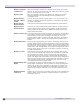
Display Transmitters
on Other Floors
When this checkbox is activated, the complete antenna system of all access
points on all floors will be visible at all times. When not checked, only access
points on the current floor will be visible.
Display Legend When this checkbox is activated, the legend in the drawing will be visible,
displaying information about the meaning of colors of partitions and of
visualization results.
Display Extension
Channels in Offset
Format
Check to display the channels in offset format ( +1/-1). If this option is not
selected, the extension channels are displayed in number format. By default,
this option is unchecked.
Display Azimuth
Antenna Patterns
Check this box to display the azimuth antenna footprint of visible antennas.
Display Elevation
Antenna Patterns
Check this box to display the elevation antenna footprint of visible antennas.
NOTE: If both the Display Azimuth Antenna Patterns and Display Elevation
Antenna Patterns are activated, Summit WMScanner displays the full three-
dimensional antenna pattern.
Radius of Patterns (m) If you have chosen to display antenna patterns, this number is the outer radius
of the pattern. Adjusting this setting controls the perceived size in meters of
antenna patterns on the screen. Increasing or decreasing the size of the
displayed antenna pattern is useful for very large drawing files. Enlarging the
antenna patterns makes it easier to spot current antenna placement while
zoomed.
Display Ceiling Tiles Check this box to display ceiling tiles placed in the drawing. Ceiling tiles are
triangular surface entities that define the boundaries of the ceiling separating
each floor of the building. Using this checkbox, you can select to either view or
hide ceiling tiles. This functionality is useful to visualize where elevator shafts,
auditoriums, or other building features are positioned. Ceiling tiles are used to
explicitly specify ceilings if none exist in the drawing. Otherwise, ceilings are
assumed to be everywhere.
Display Floor Tiles Check this box to display floor tiles placed into the drawing. Floor tiles are
simply ceiling tiles that have been placed on the floor below the current floor
being displayed. For example, if Floor1 has had ceiling tiles specified for it
and you adjust your view using the View > Building Floor commands to be
Floor2, if the Display Floor Tiles checkbox is set the ceiling tiles positioned for
Floor1 will be visible while you are viewing Floor2. This command is useful for
report generation purposes and for understanding what open areas on the
current floor are available to the floors below.
Default Drawing Units
Display
This dropdown list controls the default drawing units used throughout to
display lengths and distances. This only controls the settings for dialog boxes
the first time you open them. Afterwards, the settings of the individual units
selection controls within the dialog box are independently set. That is, the
settings of each dialog box remain as you last left them independent of this
flag.
Equipment Related
Scale Factor
Changes the size of the icons on the screen with respect to value provided.The
setting is global, and the scale factor is applied equally to all access points,
RFID devices and so on.