Network Design Reference for Avaya Virtual Services Platform 4000 Series Release 4.2.1 NN46251-200 Issue 07.
© 2015 Avaya Inc. All Rights Reserved. Notice While reasonable efforts have been made to ensure that the information in this document is complete and accurate at the time of printing, Avaya assumes no liability for any errors. Avaya reserves the right to make changes and corrections to the information in this document without the obligation to notify any person or organization of such changes.
result in substantial additional charges for your telecommunications services. Avaya Toll Fraud intervention If You suspect that You are being victimized by Toll Fraud and You need technical assistance or support, call Technical Service Center Toll Fraud Intervention Hotline at +1-800-643-2353 for the United States and Canada. For additional support telephone numbers, see the Avaya Support website: http://support.avaya.com or such successor site as designated by Avaya.
Contents Chapter 1: Introduction............................................................................................................ 7 Purpose.................................................................................................................................. 7 Related resources................................................................................................................... 7 Support.......................................................................................
Contents Loop prevention and detection................................................................................................ 43 SLPP example scenarios....................................................................................................... 45 Chapter 9: Layer 2 switch clustering and SMLT.................................................................. 50 Split MultiLink Trunk configuration..........................................................................................
Contents Multicast MAC filtering......................................................................................................... 131 Guidelines for multicast access policies................................................................................. 132 Split-subnet and multicast.................................................................................................... 132 Protocol Independent Multicast-Sparse Mode guidelines........................................................
Chapter 1: Introduction Purpose This document provides information on features in VSP Operating System Software (VOSS). VOSS runs on the following product families: • Avaya Virtual Services Platform 4000 Series • Avaya Virtual Services Platform 7200 Series • Avaya Virtual Services Platform 8000 Series This document provides information to help you build robust and efficient networks using the Avaya Virtual Services Platform 4000 Series .
Introduction About this task Videos are available on the Avaya Support website, listed under the video document type, and on the Avaya-run channel on YouTube. Procedure • To find videos on the Avaya Support website, go to http://support.avaya.com and perform one of the following actions: - In Search, type Avaya Mentor Videos to see a list of the available videos. - In Search, type the product name. On the Search Results page, select Video in the Content Type column on the left.
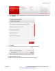
Related resources 5. In the GENERAL NOTIFICATIONS area, select the required documentation types, and then click UPDATE. 6. Click OK. 7. In the PRODUCT NOTIFICATIONS area, click Add More Products. 8. Scroll through the list, and then select the product name. 9. Select a release version. 10. Select the check box next to the required documentation types. June 2015 Network Design Reference for Avaya VSP 4000 Series Comments on this document? infodev@avaya.
Introduction 11. Click Submit. Support Go to the Avaya Support website at http://support.avaya.com for the most up-to-date documentation, product notices, and knowledge articles. You can also search for release notes, downloads, and resolutions to issues. Use the online service request system to create a service request. Chat with live agents to get answers to questions, or request an agent to connect you to a support team if an issue requires additional expertise.
Support 3. In the Search dialog box, select the option In the index named .pdx. 4. Enter a search word or phrase. 5. Select any of the following to narrow your search: • Whole Words Only • Case-Sensitive • Include Bookmarks • Include Comments 6. Click Search. The search results show the number of documents and instances found. You can sort the search results by Relevance Ranking, Date Modified, Filename, or Location. The default is Relevance Ranking.
Chapter 2: New in this release The following sections detail what is new in Network Design Reference for Avaya Virtual Services Platform 4000 Series, NN46251-200. VOSS 4.2.1 Features See the following sections for information about feature-related changes. Loop prevention and detection For VOSS 4.2.1, references to Loop Detect have been removed from the section Loop prevention and detection on page 43.
VOSS 4.2 VOSS 4.2 Features See the following section for information about feature-related changes in VOSS 4.1. Features for VSP Operating System Software (VOSS)4.1 • IPv6 VSP 4000 VOSS 4.2 provides support for IPv6 routing. File Transfer Protocol (FTP), Trivial File Transfer Protocol (TFTP), Hypertext Transfer Protocol (HTTP) and Hypertext Transfer Protocol Secure (HTTPS) now support both IPv4 and IPv6 addresses, with no difference in functionality or configuration. VSP 4000 VOSS 4.
New in this release • RSMLT and SMLT with virtual IST Split MultiLink Trunking (SMLT) provides subsecond failover when a switch fails. Routed Split MultiLink Trunking (RSMLT) permits rapid failover for core topologies by providing an activeactive router concept to core SMLT networks. Virtual Inter-Switch Trunk (vIST) improves on this resiliency by using a virtualized IST channel through the SPBM Cloud.
VOSS 4.2 VOSS 4.2 does not support Secure Copy (SCP). For this release, use SFTP to transfer files securely. For more information, see the section “Security overview” in Security for Avaya Virtual Services Platform 4000 Series, NN46251-601. • SNMPv3 VOSS 4.2 updates SNMPv3 to support Federal Information Processing Standards (FIPS) 140-2.
Chapter 3: Network design fundamentals To efficiently and cost-effectively use Avaya Virtual Services Platform 4000 Series, you must properly design your network, which includes the following considerations: • Reliability and availability • Platform redundancy • Desired level of redundancy A robust network depends on the interaction between system hardware and software. System software can be divided into different functions as shown in the following figure.
Based on network problem-tracking statistics, the following list is an approximate stability estimation model of a system that uses these components: • Hardware and drivers represent a small portion of network problems. • Local software represents a more significant share. • Interacting software represents the vast majority of the reported issues. Based on this model, network design attempts to off-load the interacting software level as much as possible to the other levels, especially to the hardware level.
Chapter 4: Hardware fundamentals and guidelines This chapter provides general hardware guidelines to use the Avaya Virtual Services Platform 4000 Series in a network. Use the information in this chapter to help you during the hardware design and planning phase. Supported hardware VOSS 4.2.1 supports the following VSP 4000 Series models: 1. VSP 4850GTS Series: Includes the 4850GTS (AC), the 4850GTS-PWR+, and the 4850GTSDC. 2.
Platform considerations Note: The 300W and 1000 W AC power supplies use the IEC 60320 C16 AC power cord connector. Use the order codes to order a replacement for the primary PSU or to order a redundant PSU for your VSP 4000 system. Table 1: Power supply order codes VSP 4000 PSU Usage Part number (order code) 300 W AC power supply For use in the ERS 4626GTS, VSP 4850GTS and WL8180, WL8180-16L wireless controllers.
Hardware fundamentals and guidelines This device is a Class A product. Operation of this equipment in a residential area is likely to cause harmful interference, in which case users are required to take appropriate measures necessary to correct the interference at their own expense. Power specifications for VSP 4000 switches 4850GTS series and 4450GSX series The following sections describe the regulatory AC and DC power specifications for the VSP 4000 series switches.
Platform considerations Table 3: AC power specifications for 4450GSX-PWR+ 4450GSX-PWR+ Input Current 16.66 A/8.33 A Input Voltage (rms) 100 to 240 VAC at 50 to 60 Hz Power Consumption • Without PoE+ - Typical: 116 W - Maximum: 164.6 W • With PoE+ - Typical power utilization depends on the number of ports using PoE+. - Maximum: 553.
Hardware fundamentals and guidelines 1000 W AC power supply VSP 4000 PWR+ model (4450GSX-PWR+) supports dual 54 V 1000 W PoE+ AC power supplies. Important: Ensure that you use only 1000 W power supplies (both primary and secondary) on VSP 4000 PWR+ models. Figure 2: 1000 W AC power supply 300 W AC power supply The Avaya VSP 4850GTS supports 300 W AC power supplies. Figure 3: 300 W AC power supply 22 Network Design Reference for Avaya VSP 4000 Series Comments on this document? infodev@avaya.
Platform considerations Connector The 300 W and 1000 W AC power supplies use an IEC 60320 C16 AC power cord connector. The AC power cord is in close proximity to the hot-air exhaust, and supports high operating temperatures. The 1000 W AC power supplies use an IEC 60320 C16 AC power cord connector. The AC power cord is in close proximity to the hot-air exhaust, and supports high operating temperatures.
Hardware fundamentals and guidelines PoE+ support on 0°C to 50°C 50°C to 70°C 26 ports 13 ports Avaya VSP 4450GTX-HT-PWR+ model with 2 PSUs PoE support on 48 ports 48 ports PoE+ support on 48 ports 26 ports • VSP 4450GTX-HT-PWR+ can support 802.3af 17.8W or 32.4W on each port with one power supply installed. You can add a second power supply for redundancy. DC power supply specifications The following table describes the DC power supply specifications for the VSP 4000.
Hardware compatibility for VSP 4000 Release VSP 4000 model Description • two 1/10GE SFP+ ports • Base Software License • one (of two) field replaceable 1000W PSUs supplied with the chassis 3.0 VSP 4850GTS DC • 48 10/100/1000 Base TX RJ-45 ports Part number Note: Replace the “x” with a countryspecific power cord code. See the footnote for details. EC4800078-E6 • two shared SFP ports • two 1/10GE SFP+ ports • one (of two) field replaceable 300W DC PSUs supplied with the chassis 4.
Hardware fundamentals and guidelines Release VSP 4000 model Description • Two 1/10G SFP+ ports with MACsec capable PHY • One (of two) field-replaceable 1000W PSUs supplied with the chassis Part number Note: Replace the “x” with a countryspecific power cord code. See the footnote for details. Note: The character (x) in the order number indicates the power cord code. Replace the “x” with the proper letter to indicate the desired product nationalization.
Dispersion considerations for long reach For more information about SFP and SFP+ transceivers, including technical specifications and installation instructions, see Installing Transceivers and Optical components on Avaya Virtual Services Platform 4000 Series, NN46251-301. Optical power considerations When you connect the device to collocated equipment, ensure that enough optical attenuation exists to avoid overloading the receivers of each device.
Hardware fundamentals and guidelines The sum of margin, dispersion power penalty, and passive cable plant losses must be less than the available power budget. Alternatively, if you calculate available power margin as the difference between the available budget and the sum of losses and dispersion, the margin can be more or less than required, which determines whether additional consideration is needed.
Auto MDIX Port on A Port on B Remarks Recommendations both ports support AutoNegotiation mode. Full-duplex Full-duplex Both sides require the same Avaya recommends that mode. you use this configuration if you require full-duplex, but the configuration does not support Auto-Negotiation. Auto-Negotiation cannot detect the identities of neighbors or shut down misconnected ports. Upperlayer protocols perform these functions.
Hardware fundamentals and guidelines CANA Use Custom Auto-Negotiation Advertisement (CANA) to control the speed and duplex settings that the interface modules advertise during Auto-Negotiation sessions between Ethernet devices. Modules can only establish links using these advertised settings, rather than at the highest common supported operating mode and data rate. Use CANA to provide smooth migration from 10/100 Mbps to 1000 Mbps on host and server connections.
Chapter 5: Optical routing design The Avaya optical routing system uses coarse wavelength division multiplexing (CWDM) in a grid of eight optical wavelengths. Use the Avaya optical routing system to maximize bandwidth on a single optical fiber. This chapter provides optical routing system information that you can use to help design your network.
Optical routing design • Optical add/drop multiplexers (OADM) • Optical multiplexer/demultiplexers (OMUX) • Optical shelf to house the multiplexers OADMs drop or add a single wavelength from or to an optical fiber. For the list of supported optical devices on the Avaya Virtual Services Platform 4000 Series platform for the current release, see Supported optical devices on page 26. 32 Network Design Reference for Avaya VSP 4000 Series Comments on this document? infodev@avaya.
Chapter 6: Platform redundancy This chapter includes recommendations to provide a fault-tolerant platform. Power redundancy The Avaya VSP 4000 series PWR+ models support dual 54V 1000W Power over Ethernet Plus (PoE+) AC power supplies. This model supports two external field-replaceable power supplies. You can install a secondary power supply to provide redundancy and load sharing, and add Power over Ethernet Plus (PoE+) power budget on PWR+ models.
Platform redundancy Maximum PoE+ W 1835 W with two power supplies Average PoE+ W on 12 ports • VSP 4450GSX-PWR+ can support 802.3af 17.8 W or 32.4 W on each port with one power supply installed. You can add a second power supply for redundancy.
Link redundancy Link redundancy Provide physical and link layer redundancy to eliminate a single point of failure in the network. For more information, see Link redundancy on page 36. June 2015 Network Design Reference for Avaya VSP 4000 Series Comments on this document? infodev@avaya.
Chapter 7: Link redundancy You can build link redundancy into your network to: • Help eliminate a single point of failure in your network (provide physical and link layer redundancy) • Prevent a service interruption caused by a faulty link (provide link layer redundancy) This chapter explains the following design options that you can use to achieve link redundancy (provide alternate data paths) : • Physical layer redundancy • MultiLink Trunking • 802.
Physical layer redundancy Figure 6: 1000BASE-X RFI End-to-end fault detection and VLACP Because remote fault indication (RFI) terminates at the next Ethernet hop, the device that uses only RFI cannot determine failures on an end-to-end basis over multiple hops. However, you can use Virtual Link Aggregation Control Protocol (VLACP) to provide an end-to-end failure detection mechanism. You can configure VLACP on a port and enable it over single links or multilink trunks (MLT).
Link redundancy To minimize network outages, you can also use VLACP to switch traffic around entire network devices before Layer 3 protocols detect a network failure. VLACP is an extension of the Link Aggregation Control Protocol (LACP) but LACP and VLACP are independent features. VLACP does not perform link aggregation; it detects end-to-end link failures.
Physical layer redundancy Figure 8: Problem description (2 of 2) However, if you use VLACP to detect far-end failures and allow MLT to fail over when end-to-end connectivity is not guaranteed for links in an aggregation group, VLACP prevents the failure scenario in the preceding figure. Avaya recommends that you use the following guidelines for VLACP implementation: • Do not use VLACP on configured LACP MLTs because LACP provides the same functionality as VLACP for link failure.
Link redundancy end-to-end perspective. If a particular link does not receive VLACP PDUs, the platform shuts the link down after the expiry time-out occurs (time-out scale x periodic time). As a result of this action the ports stay in a disabled state. MultiLink Trunking Use MLT to provide link-layer redundancy. You can use MLT to provide alternate paths around failed links. When you configure MLT links, consider the following information: • The device supports 24 MLT aggregation groups.
802.3ad-based link aggregation Table 15: Path cost for RSTP or MSTP mode Link speed Recommended path cost Less than or equal 100 Kbps 200 000 000 1 Mbps 20 000 000 10 Mbps 2 000 000 100 Mbps 200 000 1 Gbps 20 000 10 Gbps 2000 100 Gbps 200 1 Tbps 20 10 Tbps 2 802.3ad-based link aggregation Link aggregation provides link layer redundancy. Use IEEE 802.3ad-based link aggregation (IEEE 802.
Link redundancy LACP and spanning tree interaction Only the physical link state or the LACP peer status affects the operation of LACP. When a link changes state between UP and DOWN, the LACP module receives notification. The spanning tree forwarding state does not affect the operation of the LACP module. LACP data units (LACPDU) can be sent even if the port is in spanning tree blocking state.
Chapter 8: Layer 2 loop prevention This chapter provides information about how to use bandwidth and network resources efficiently, and to prevent Layer 2 data loops. Loop prevention and detection In certain network designs, loops can form. For example, loops can form if you have incorrect configuration or cabling. Avaya Virtual Services Platform 4000 Series uses Simple Loop Prevention Protocol (SLPP) as the solution to detect loops.
Layer 2 loop prevention Use the information in this section to understand the considerations and recommendations to configure SLPP in your network: • You must enable SLPP packet receive on each port to detect a loop. • SLPP test packets (SLPP-PDU) are forwarded for each VLAN. • SLPP-PDUs are automatically forwarded on VLAN ports configured for SLPP. • The SLPP-PDU destination MAC address is the switch MAC address, with the multicast bit set; the source MAC address is the switch MAC address.
SLPP example scenarios VLACP. VLACP takes the point-to-point hello mechanism of LACP and uses it to periodically send PDU packets to ensure end-to-end reachability and provide failure detection, across a Layer 2 domain. If one end of the link does not receive the VLACP PDUs, it logically disables that port and no traffic passes. This action ensures that even if no link exists on the port at the other end, and if it is not processing VLACP PDUs correctly, no traffic is sent.
Layer 2 loop prevention Figure 9: VSP 4000 as an edge router SLPP PDUs are generated by VSP 4000. If there is a loop, the SLPP PDUs return to port 1/1. After the threshold value is reached, SLPP shuts the ports down. Scenario 2: VSP 4000 as an edge router but with an additional link to the ERS 8800 Scenario 2 is similar to scenario 1 except that there is an additional link from ERS 8800 to VSP 4000 that is not part of MLT 1.
SLPP example scenarios Figure 10: VSP 4000 as an edge router and with an additional link with ERS 8800 The SLPP PDUs generated by VSP 4000 return to the same device through the additional link. After the threshold value set on the SLPP-enabled ports is reached, the ports are shut down. Scenario 3: VSP 4000 as a BEB connected to an edge router In scenario 3, VSP 4000 acts as a Backbone Edge Bridge (BEB) and is connected to a BayStack device.
Layer 2 loop prevention Figure 11: VSP 4000 as a BEB connected to an edge router In this scenario, either SLPP or RSTP/MSTP can shut the ports down. Scenario 4: Two VSP 4000 switches acting as BEBs In scenario 4, there are two VSP 4000 devices that act as BEBs and are connected to each other through MLT, with two BayStack devices connected to each of the BEBs. The interface that connects the VSP 4000 interfaces is an Intermediate System to Intermediate System (IS-IS) interface with STP disabled.
SLPP example scenarios Figure 12: Two VSP 4000 switches acting as BEBs The SLPP PDUs generated by the VSP 4000-1 return to itself through VSP 4000–2, Bay Stack 2, and Bay Stack 1. After reaching the threshold value, the SLPP shuts the port down, eliminating the loop. June 2015 Network Design Reference for Avaya VSP 4000 Series Comments on this document? infodev@avaya.
Chapter 9: Layer 2 switch clustering and SMLT Split MultiLink Trunking (SMLT) enables node redundancy by allowing aggregated link groups to be dual-homed across a pair of aggregating devices. This introduces an extra level of redundancy and failure protection. SMLT is introduced into existing subnetworks to provide this redundancy without the need to upgrade installed equipment.
Split MultiLink Trunk configuration Table 17: Recommended VLACP values Parameter Value SMLT access Timeout Short Timer 500ms Timeout scale 5 VLACP MAC 01:80:C2:00:00:0F SMLT core Timeout Short Timer 500ms Timeout scale 5 VLACP MAC 01:80:C2:00:00:0F vIST Timeout Long Timer 10000 Timeout scale 3 VLACP MAC 01:80:C2:00:00:0F SMLT and loop prevention SMLT-based network designs form physical loops for redundancy that logically do not function as loops.
Layer 2 switch clustering and SMLT • Simpler configuration — A Routed SMLT Layer 2 Edge configuration only requires enabling RSMLT on a VLAN. VRRP requires virtual IP configuration along with other parameters. For connections in pure Layer 3 configurations using a static or dynamic routing protocol, use a Layer 3 RSMLT configuration instead of SMLT with VRRP. RSMLT configuration provides faster failover than VRRP.
Split MultiLink Trunk configuration SMLT aggregation switches detect that aggregation is disabled on the SMLT client, thus no automatic link aggregation establishes until the configuration is resolved. • Single CPU failure In this case, LACP on other switches detects the remote failure, and all links that connect to the failed system are removed from the link aggregation group. This process allows failure recovery to a different network path.
Chapter 10: Layer 3 switch clustering and RSMLT This section describes designs for achieving network redundancy. Network redundancy minimizes failure and ensures a faulty switch does not interrupt service. Related Links Routed SMLT on page 54 Switch clustering topologies and interoperability with other products on page 61 Routed SMLT Core network convergence time usually depends on the length of time a routing protocol requires to successfully converge.
Routed SMLT Figure 13: SMLT and RSMLT in Layer 2 and 3 environments The aggregation layer switches are routing-enabled and provide active-active default gateway functions through RSMLT. Routers R1 and R2 forward traffic for IP subnet A. RSMLT provides both router and link failover. If the SMLT link between R2 and R4 breaks, the traffic fails over to R1.
Layer 3 switch clustering and RSMLT RSMLT provides superior router redundancy in core networks (for example, IP subnet B) in which OSPF is used. Routers R1 and R2 provide router backup for each other—not only for the edge IP subnet A but also for the core IP subnet B. Similarly, routers R3 and R4 provide router redundancy for IP subnet C and also for core IP subnet B.
Routed SMLT RSMLT timer tuning RSMLT enables a participating peer switch to act as a router for its peer by MAC address. This doubles router capacity and enables fast failover in the event of a peer switch failure. RSMLT provides hold-up and hold-down timer parameters to aid these functions. The hold-up timer defines the length of time the RSMLT-peer switch routes for its peer after a peer switch failure. Configure the hold-up timer to at least 1.5 times greater than the routing protocol convergence time.
Layer 3 switch clustering and RSMLT Figure 14: VLAN with all IP Deskphones as members Example: RSMLT network with static routes at the access layer Use default routes that point towards the RSMLT IP interfaces of the aggregation layer to achieve a robust redundant edge design, as shown in the following figure. Figure 15: VLAN edge configuration Example: RSMLT IPv6 network topology The following figure shows a sample IPv6 RSMLT topology.
Routed SMLT many IPv6 prefixes, one VLAN (VLAN 1, IP prefix A) spans all wiring closets. RSMLT provides the loop-free topology. The aggregation layer switches are configured with routing enabled and provide active-active default gateway functionality through RSMLT. Figure 16: IPv6 RSMLT topology In VLAN 3 of the preceding figure, routers R1 and R2 provide RSMLT-enabled IPv6 service to hosts H1 and H2. Router R1 is the default IPv6 router for H1 and R2 is the default router for H2.
Layer 3 switch clustering and RSMLT • routing prefix of 2003::/64 As a shorthand, the last two items in the preceding list are referred to as 2003::1/64. R2 uses the following configuration: • link-local address of fe80::1 • global unicast address and routing prefix if routing prefix of 2003::2/64. Host H1 sends IPv6 traffic destined to VLAN 1 to the MAC address for R1. H2 sends traffic to the MAC address for R2.
Switch clustering topologies and interoperability with other products Switch clustering topologies and interoperability with other products The switch clustering, unicast routing, and multicast routing configurations vary with switch type when using Ethernet Routing Switch products with Avaya Virtual Services Platform 4000. Use the supported topologies and features when you perform inter-product switch clustering.
Chapter 11: Layer 3 switch clustering and multicast SMLT Switch clustering is the logical aggregation of two nodes to form one logical entity known as the switch cluster. The two peer nodes in a switch cluster connect using a virtual interswitch trunk (vIST). The vIST exchanges forwarding and routing information between the two peer nodes in the cluster. This section provides guidelines for switch clusters that use multicast and Split Multilink Trunking (SMLT).
General guidelines Figure 17: Multicast behavior in SMLT environment In Multicast behavior in SMLT environment on page 63 the following actions occur: 1. The multicast server sends multicast data towards the source designated router (DR). 2. The source DR sends register messages with encapsulated multicast data towards the RP. 3. After the client sends IGMP membership reports towards the multicast router, the router creates a (*,G) entry.
Layer 3 switch clustering and multicast SMLT 4. The RP sends join messages towards the source DR on the reverse path. 5. After the source DR receives the join messages, it sends native multicast traffic. 6. After SW_B or SW_D receives multicast traffic from upstream, it forwards the traffic on the vIST as well as on the SMLT link. Other aggregation switches drop multicast traffic received over the vIST at egress. This action provides fast failover for multicast traffic.
Multicast triangle topology Figure 18: Multicast routing using PIM-SM Client switches run IGMP Snoop or PIM-SM, and the aggregation switches run PIM-SM. This design is simple and, for the rest of the network, PIM-SM performs IP multicast routing. The aggregation switches are the query devices for IGMP, so an external query device is not required to activate IGMP membership. These switches also act as redundant switches for IP multicast.
Layer 3 switch clustering and multicast SMLT Figure 19: Multicast SMLT triangle Use an edge device that supports a form of link aggregation. Disable spanning tree on the link aggregation group on the edge devices. Enable either Virtual Router Redundancy Protocol (VRRP) BackupMaster or Routed SMLT (RSMLT) Layer 2 Edge on the switch cluster core.
Square and full-mesh topology multicast guidelines Figure 20: Multicast SMLT square 1 In the preceding figure, only one of the switch cluster cores performs Layer 3 multicast routing while the other is strictly Layer 2. Configure multiple VLANs on the edge devices, 802.1Q tagged to the switch cluster cores. Use an edge device that supports a form of link aggregation. Disable spanning tree on the link aggregation group on the edge devices.
Layer 3 switch clustering and multicast SMLT Figure 21: Multicast SMLT square 2 In the preceding figure, both of the switch cluster cores performs Layer 3 multicast routing, while the edge devices are Layer 2 IGMP. Use an edge device that supports a form of link aggregation. Disable spanning tree on the link aggregation group on the edge devices. Enable either the VRRP BackupMaster or RSMLT Layer 2 Edge on the switch cluster cores. Do not enable VRRP on the RSMLT VLAN between switch cluster cores.
SMLT and multicast traffic issues Figure 22: Multicast SMLT square 3 In the preceding figure, both of the switch cluster cores and the edge devices perform Layer 3 multicast routing. Use an edge device that supports a form of link aggregation. Disable spanning tree on the link aggregation group on the edge devices. Enable either the VRRP BackupMaster or RSMLT Layer 2 Edge on the switch cluster cores. Do not enable VRRP on the RSMLT VLAN between switch cluster cores.
Layer 3 switch clustering and multicast SMLT exception. When using PIM-SM and a unicast routing protocol, ensure the unicast route to the BSR and RP has PIM-SM active and enabled. If multiple OSPF paths exist and PIM-SM is not active on each pair, the BSR is learned on a path that does not have PIM-SM active. The following figure demonstrates this issue. Figure 23: Unicast route example The network configuration in the preceding figure is as follows: • 5510A is on VLAN 101. • 5510B is on VLAN 102.
SMLT and multicast traffic issues Layer 3 switch clustering and multicast SMLT on page 62 June 2015 Network Design Reference for Avaya VSP 4000 Series Comments on this document? infodev@avaya.
Chapter 12: Spanning tree Spanning tree prevents loops in switched networks. Avaya Virtual Services Platform 4000 Series supports Rapid Spanning Tree Protocol (RSTP) and Multiple Spanning Tree Protocol (MSTP). This chapter describes issues to consider when you configure spanning tree protocols. For more information about spanning tree protocols, see Configuring VLANs and Spanning Tree on Avaya Virtual Services Platform 4000 Series, NN46251-500.
MSTP and RSTP considerations Figure 24: VLAN isolation MSTP and RSTP considerations The Spanning Tree Protocol (STP) provides loop protection and recovery, but it is slow to respond to a topology change in the network (for example, a dysfunctional link in a network). RSTP (IEEE 802.1w) and MSTP (IEEE 802.1s) reduce the recovery time after a network failure. RSTP and MSTP also maintain a backward compatibility with IEEE 802.1D. Typically, the recovery time of RSTP and MSTP is less than 1 second.
Spanning tree RSTP and MSTP provide a global spanning tree parameter, called version, for backward compatibility with legacy STP. You can configure version to either STP-compatible mode, RSTP mode, or MSTP mode: • An STP-compatible port transmits and receives only STP Bridge Protocol Data Units (BPDU). An RSTP or MSTP BPDU that the port receives in this mode is discarded. • An RSTP or MSTP port transmits and receives only RSTP or MSTP BPDUs.
Chapter 13: Layer 3 network design This chapter describes Layer 3 design considerations that you need to understand to properly design an efficient and robust network. VRF Lite The Avaya Virtual Services Platform 4000 Series supports the Virtual Routing and Forwarding (VRF) Lite feature, which supports many virtual routers, each with its own routing domain. VRF Lite virtualizes the routing tables to form independent routing domains, which eliminates the need for multiple physical routers.
Layer 3 network design VRF Lite architecture examples VRF Lite enables a router to act as many routers. This provides virtual traffic separation for each user and provides security. For example, you can use VRF Lite to: • Provide different departments within a company with site-to-site connectivity as well as Internet access • Provide centralized and shared access to data centers. The following figure shows how VRF Lite can emulate VPNs.
Virtual Router Redundancy Protocol access the Internet, data storage, VoIP-PSTN, or call signaling services. To interconnect VRF instances, you can use an external firewall that supports virtualization, or use inter-VRF forwarding for specific services. Using the inter-VRF solution, you can use routing policies and static routes to inject IP subnets from one VRF instance to another, and filters to restrict access to certain protocols. The following figure shows inter-VRF forwarding.
Layer 3 network design BackupMaster routes all traffic received on the BackupMaster IP interface according to the switch routing table. Figure 28: VRRP with BackupMaster Avaya recommends that you stagger VRRP instances on a network or subnet basis. The following figure shows the VRRP Masters and BackupMasters for two subnets.
Virtual Router Redundancy Protocol holddown timer to a minimum of 1.5 times the IGP convergence time is sufficient. For OSPF, Avaya recommends that you use a value of 90 seconds if you use the default OSPF timers. • Implement VRRP BackupMaster for an active-active configuration (BackupMaster works across multiple switches that participate in the same VRRP domain). • Configure VRRP priority as 200 to configure VRRP Master.
Layer 3 network design In this figure, configuration A is optimal because VRRP convergence occurs within 2 to 3 seconds. In configuration A, three spanning tree instances exist and VRRP runs on the link between the two routers. Spanning tree instance 2 exists on the link between the two routers, which separates the link between the two routers from the spanning tree instances found on the other devices. All uplinks are active.
Open Shortest Path First Figure 32: Avoiding excessive ICMP redirect messages without SMLT Open Shortest Path First Use OSPF to ensure that the switch can communicate with other OSPF routers. This section describes some general design considerations and presents a number of design scenarios for OSPF. For more information about OSPF concepts and configuration, see Configuring OSPF and RIP on Avaya Virtual Services Platform 4000 Series, NN46251-506.
Layer 3 network design • 5 adjacencies with an LSA_CNT of 200 (Area 3) Calculate the number as follows: 3*500+10*1000+5*200=12.5K < 16K This configuration ensures that the switch operates within accepted scalability limits. OSPF design guidelines Follow these additional OSPF guidelines: • OSPF timers must be consistent across the entire network. • Use OSPF area summarization to reduce routing table sizes. • Use OSPF passive interfaces to reduce the number of active neighbor adjacencies.
Open Shortest Path First Figure 33: Example 1: OSPF on one subnet in one area The routers in the preceding figure use the following configuration: • S1 has an OSPF router ID of 1.1.1.1, and the OSPF port uses an IP address of 192.168.10.1. • S2 has an OSPF router ID of 1.1.1.2, and the OSPF port uses an IP address of 192.168.10.2. The general method to configure OSPF on each routing switch is: 1. Enable OSPF globally. 2. Enable IP forwarding on the switch. 3.
Layer 3 network design The routers in example 2 use the following configuration: • S1 has an OSPF router ID of 1.1.1.1, and the OSPF port uses an IP address of 192.168.10.1. • S2 has an OSPF router ID of 1.1.1.2, and two OSPF ports use IP addresses of 192.168.10.2 and 192.168.20.1. • S3 has an OSPF router ID of 1.1.1.3, and the OSPF port uses an IP address of 192.168.20.2. The general method to configure OSPF on each routing switch is: 1. Enable OSPF globally. 2.
Border Gateway Protocol 2. Configure OSPF on one network. On S1, insert the IP address, subnet mask, and VLAN ID for the OSPF port. Enable OSPF on the port. On S2, insert the IP address, subnet mask, and VLAN ID for the OSPF port in area 1, and enable OSPF on the port. Both routable ports belong to the same network. Therefore, by default, both ports are in the same area. 3. Configure three OSPF areas for the network. 4. Configure OSPF on two additional ports in a second subnet.
Layer 3 network design BGP implementation guidelines To successfully implement BGP in a VSP 4000 network, follow these guidelines: • BGP does not operate with an IP router in nonforwarding (host-only) mode. Ensure that the routers with which you want BGP to operate are in forwarding mode. • If you use BGP for a multihomed AS (one that contains more than a single exit point), Avaya recommends that you use OSPF for the IGP, and BGP for the sole exterior gateway protocol. Otherwise, use intra-AS iBGP routing.
Border Gateway Protocol BGP and Internet peering By using BGP, you can perform Internet peering directly between VSP 4000 and another edge router. In such a scenario, you can use each VSP 4000 for aggregation and link it with a Layer 3 edge router, as shown in the following figure. Figure 36: BGP and Internet peering In cases where the Internet connection is single-homed, to reduce the size of the routing table, Avaya recommends that you advertise Internet routes as the default route to the IGP.
Layer 3 network design Figure 38: BGP and edge aggregation BGP and ISP segmentation You can use the platform as a peering point between different regions or ASs that belong to the same ISP. In such cases, you can define a region as an OSPF area, an AS, or a part of an AS. You can divide the AS into multiple regions that each run different IGPs. Interconnect regions logically by using a full iBGP mesh. Each region then injects its IGP routes into iBGP and also injects a default route inside the region.
Border Gateway Protocol In the preceding figure, consider the following: • The AS is divided into three regions that each run different and independent IGPs. • Regions logically interconnect by using a full-mesh iBGP, which also provides Internet connectivity. • Internal non-BGP routers in each region default to the BGP border router, which contains all routes.
Layer 3 network design Figure 41: Multiple OSPF regions peering with the Internet IP routed interface scaling VSP 4000 supports up to 256 IP-routed interfaces. When you configure a large number of IP-routed interfaces, use passive interfaces on most of the configured interfaces. You can make very few interfaces active. IPv6 IPv6 provides high-performance, scalable Internet communications. Use the information in this section to help deploy IPv6 in your network.
IPv6 Tunneling The switch supports manually configured IPv6-in-IPv4 tunnels per RFC4213. A manually-configured tunnel is equivalent to a permanent link between two IPv6 domains over an IPv4 backbone. Use tunnels to provide stable, secure communications between two edge routers, an end system and an edge router, or to provide a connection to remote IPv6 networks. Configure an IPv6 address on the tunnel interface. Configure an IPv4 address on the tunnel source and destination.
Layer 3 network design increasing ND traffic, especially when many hosts try to determine the reachability of one of more routers. To provide fast failover of a default router for IPv6 LAN hosts, the switch supports the Virtual Router Redundancy Protocol (VRRP) for IPv6 VRRP for IPv6 provides a faster switchover to an alternate default router than is possible using the ND protocol.
Chapter 14: SPBM design guidelines Shortest Path Bridging MAC (SPBM) is a next-generation virtualization technology that revolutionizes the design, deployment, and operations of enterprise edge campus core networks and data centers. The benefits of the technology are clearly evident in its ability to provide massive scalability while at the same time reducing the complexity of the network.
SPBM design guidelines IS-IS interfaces operate in point-to-point mode only, which means that for any port or MLT interface where IS-IS is enabled, there can be only one IS-IS adjacency across that interface. B-MAC An SPBM backbone includes Backbone Edge Bridges (BEB) and Backbone Core Bridges (BCB). A BEB performs the same functionality as a BCB, but it also terminates one or more Virtual Service Networks (VSNs). A BCB does not terminate any VSNs.
VLANs without member ports The following figure shows the components of a basic SPBM architecture. Figure 43: SPBM basic architecture VLANs without member ports The Avaya Ethernet Routing Switch 8800 manages VLANs without member ports differently than the Virtual Services Platform 9000 and Virtual Services Platform 4000. • The Ethernet Routing Switch 8800 always designates the VLAN as operationally up if there is an attached I-SID.
SPBM design guidelines When the VLAN is operationally up, the IP address of the VLAN will be in the routing table. • If no matching instance of the I-SID exists in the SPBM network, then that VLAN has no reachable members and does not act as an NNI interface. The VLAN does not act as a UNI interface because it does not have a member port. Therefore, the device does not designate the VLAN as operationally up because the VLAN does not act as a UNI or an NNI interface.
Implementation options IP multicast over Fabric Connect Provisioning IP multicast over Fabric Connect is as simple as enabling multicast over Fabric Connect on the BEBs. You do not need to enable IP multicast over Fabric Connect on the BCBs. For Layer 2 VSN using IP multicast over Fabric Connect, configure Internet Group Management Protocol (IGMP) snooping on the VLAN that represents the Layer 2 VSN.
SPBM design guidelines Figure 45: SPBM implementation options The following sections describe the options that are illustrated in the preceding figure. A—IP shortcut IP shortcuts forward standard IP packets over IS-IS. This option enables you to forward IP over the SPBM core, which is a simpler method than traditional IP routing or MPLS.
Implementation options In Figure 45: SPBM implementation options on page 98, node VSP-G acts as a BCB for the service, and has no IP configuration. B—Layer 2 VSN A Layer 2 Virtual Services Network (VSN) bridges customer VLANs (C-VLANs) over the SPBM core infrastructure. A Layer 2 VSN associates a C-VLAN with an I-SID, which is then virtualized across the backbone. All VLANs in the network that share the same I-SID can participate in the same VSN.
SPBM design guidelines advertising their reachable IP routes into IS-IS and installing IP routes learned from IS-IS. Suitable IP redistribution policies need to be defined to determine what IP routes a BEB will advertise to ISIS. As seen in Figure 45: SPBM implementation options on page 98, the green VRF on VSP-C is configured to advertise its local or direct IP routes into IS-IS within I-SID 13990001.
Implementation options Figure 46: Multi-tenant SPBM metro network To illustrate the versatility and robustness of SPBM even further, the following figure shows a logical view of multiple tenants in a ring topology. In this architecture, each tenant has its own domain where some users have VLAN requirements and are using Layer 2 VSNs and others have VRF requirements and are using Layer 3 VSNs. In all three domains, they can share data center resources across the SPBM network.
SPBM design guidelines Figure 47: SPBM ring topology with shared data centers Reference architectures SPBM has a straightforward architecture that simply forwards encapsulated C-MACs across the backbone. Because the B-MAC header stays the same across the network, there is no need to swap a label or perform a route lookup at each node. This architecture allows the frame to follow the most efficient forwarding path from end to end.
Reference architectures Figure 48: SPBM basic architecture Provisioning an SPBM core is as simple as enabling SPBM and IS-IS globally on all the nodes and on the core facing links. To migrate an existing edge configuration into an SPBM network is just as simple. The boundary between the MAC-in-MAC SPBM domain and the 802.1Q domain is handled by the BEBs. At the BEBs, VLANs or VRFs are mapped into I-SIDs based on the local service provisioning.
SPBM design guidelines Figure 49: Access to the SPBM Core For Layer 2 virtualized bridging (Layer 2 VSN), identify all the VLANs that you want to migrate into SPBM and assign them to an I-SID on the BEB. For Layer 3 virtualized routing (Layer 3 VSN), map IPv4-enabled VLANs to VRFs, create an IP VPN instance on the VRF, assign an I-SID to the VRF, and then configure the desired IP redistribution of IP routes into IS-IS. All BEBs that have the same I-SID configured can participate in the same VSN.
Reference architectures SMLT If your existing edge configuration uses SMLT, you can maintain that SMLT-based resiliency for services configured on the vIST peer switches. SPBM requires that you upgrade both vIST peer to the current release and identify two VLANs to use as B-VLANs. SPBM then automatically creates a virtual backbone MAC for the vIST pair, and advertises it with IS-IS.
SPBM design guidelines Figure 50: SPBM campus without SMLT After you migrate all services to SPBM, the customer VLANs (C-VLANs) will exist only on the BEB SMLT clusters at the edge of the SPBM network. The C-VLANs will be assigned to an I-SID instance and then associated with either a VLAN in an Layer 2 VSN or terminated into a VRF in an Layer 3 VSN. You can also terminate the C-VLAN into the default router, which uses IP shortcuts to IP route over the SPBM core.
Reference architectures The following figure uses IP shortcuts that route VLANs. There is no I-SID configuration and no Layer 3 virtualization between the edge distribution and the core. This is normal IP forwarding to the BEB. Figure 51: IP shortcut scenario to move traffic between data centers The following figure uses Layer 3 VSNs to route VRFs between the edge distribution and the core. The VRFs are attached to I-SIDs and use Layer 3 virtualization.
SPBM design guidelines Figure 52: VRF scenario to move traffic between data centers Multicast architecture Networks today either have inefficient bridged IP multicast networks (Internet Group Management Protocol, or IGMP) or IP multicast networks that require multiple protocols that are complex to configure and operate.
Reference architectures multicast over Fabric Connect enabled, only receivers that are part of the same Layer 2 VSN can receive that stream. Similarly, if a sender transmits a multicast stream to a BEB on a VLAN that is part of the Layer 3 VSN with IP multicast over Fabric Connect enabled, only receivers that are part of the same Layer 3 instance can receive that stream. IP multicast over Fabric Connect uses BEBs to act as senders and receivers of data.
SPBM design guidelines Figure 53: IP multicast over Fabric Connect streams The following steps describe how multicast senders and receivers connect to the SPBM cloud using BEBs, as illustrated in the preceding figure: 1. The sender sends multicast traffic with group IP address 233.252.0.1. 2. After the BEB receives the IP multicast stream from the sender, the BEB allocates data I-SID 16000001 for the S,G multicast stream.
Reference architectures Large data center architecture SPBM supports data centers with IP shortcuts, Layer 2 VSNs, or Layer 3 VSNs. If you use vMotion, you must use Layer 2 between data centers (Layer 2 VSN). With Layer 2 VSNs, you can add IP addresses to the VLAN on both data centers and run Virtual Router Redundancy Protocol (VRRP) between them to allow the ESX server to route to the rest of the network. The following figure shows an SPBM topology of a large data center.
SPBM design guidelines Figure 55: Traditional routing before moving VMs A VM is a virtual server. When you move a VM, the virtual server is moved as is. This action means that the IP addresses of that server remain the same after the server is moved from one data center to the other. This in turn dictates that the same IP subnet (and hence VLAN) exist in both data centers. In the following figure, the VM moved from the data center on the left to the data center on the right.
Reference architectures Figure 56: Traditional routing after moving VMs Optimized data center routing of VMs: Two features make a data center optimized: • VLAN routers in the Layer 2 domain (green icons) • VRRP BackupMaster The VLAN routers use lookup tables to determine the best path to route incoming traffic (red dots) to the destination VM. VRRP BackupMaster solves the problem of traffic congestion on the vIST. Because there can be only one VRRP Master, all other interfaces are in backup mode.
SPBM design guidelines Figure 57: Optimized routing before moving VMs In the traditional data center, chaos resulted after many VMs were moved. In an optimized data center as shown in the following figure, the incoming traffic enters the Layer 2 domain where an edge switch uses Inter-VSN routing to attach an I-SID to a VLAN. The I-SID bridges traffic directly to the destination.
Solution-specific reference architectures Figure 58: Optimized routing after moving VMs Solution-specific reference architectures The following sections describe solution-specific reference architectures, like for example for Video Surveillance or Data Center implementation, using the VSP 4000. Multi-tenant — fabric connect This fabric connect-based solution leverages the fabric capabilities of the VSP platforms: a VSP 7000 core and a VSP 4000 edge.
SPBM design guidelines Figure 59: Small core — multi-tenant The following list outlines the benefits of the fabric connect-based solution: • Endpoint provisioning • Fast failover • Simple to configure • L2 and L3 virtualized Hosted data center management solution — ETREE In some hosted data center solutions, the hosting center operating company takes responsibility for managing customer servers.
Solution-specific reference architectures Figure 60: Data center hosting private VLAN The following list outlines the benefits of the hosted data center management solution: • Easy endpoint provisioning • Optimal resiliency • Secure tenant separation Video surveillance — bridged In a video surveillance solution, optimal traffic forwarding is a key requirement to ensure proper operation of the camera and recorder solutions. However, signaling is also important to ensure quick channel switching.
SPBM design guidelines Figure 61: Deployment scenario — bridged video surveillance and IP camera deployment for transportation, airports, and government The following list outlines the benefits of the bridged video surveillance solution: • Easy end-point provisioning • sub second resiliency and mc forwarding • secure tenant separation • quick camera switching Video surveillance — routed In a video surveillance solution, optimal traffic forwarding is a key requirement to ensure proper operation of the cam
Solution-specific reference architectures Figure 62: Deployment scenario — Routed video surveillance and IP camera deployment for transportation, airports, and government The following list outlines the benefits of the routed video surveillance solution: • Easy endpoint provisioning • Optimal resiliency and mc forwarding • Secure tenant separation • Rapid channel/camera switching Metro-Ethernet Provider solution VSP 9000, ERS 8000, VSP 7000 and VSP 4000 provide an end-to-end Metro-Ethernet Provider solut
SPBM design guidelines Figure 63: Metro ring access solution The following list outlines the benefits of the Metro-Ethernet Provider solution: • Easy endpoint provisioning • Optimal resiliency • Secure tenant separation Best practices This section provides best practices to configure an SPBM network. IS-IS The following list identifies best practices for IS-IS: • Avaya recommends that you change the IS-IS system ID from the default B-MAC value to a recognizable address to easily identify a switch.
Best practices practice as adding a second B-VLAN to an existing configuration allows SPBM to load balance traffic across two equal-cost multipaths if the physical topology grants it. • In a ring topology with OSPF and IS-IS configured in the core, a core link break causes slow convergence that can lead to SPBM Layer 2 traffic loss. If the last member link of an OSPF VLAN fails, it takes down the IP interface and OSPF reconverges.
SPBM design guidelines mep : mip : (level 4) isis manual area : 49.0001 SPBM restrictions and limitations This section describes the restrictions and limitations associated with SPBM on VSP 4000. RSTP and MSTP The following list identifies restrictions and limitations associated with RSTP and MSTP: • RSTP mode does not support SPBM.
IP multicast over Fabric Connect restrictions IS interfaces. The default values for these commands work well for most networks, including those using moderately scaled routes. In highly scaled networks, you may need to configure higher values for these commands. VLACP VLACP is generally used when a repeater or switch exists between connected VSP 4000 switches to detect when a connection is not operational even when the link LED is lit.
SPBM design guidelines Data I-SID The BEB matches a single multicast stream to a particular data I-SID. As a result there is a one-toone mapping between the source, group (S,G) pair to data I-SID for each BEB. IP address In this release, IP multicast over Fabric Connect supports only IPv4 multicast traffic. Supported services VSP 4000 does not support IP multicast over Fabric Connect routing on inter-VSN routing interfaces.
Chapter 15: IP multicast network design Use multicast routing protocols to efficiently distribute a single data source among multiple users in the network. This section provides information about how to design networks that support IP multicast routing. For more information about multicast routing, see Configuring IP Multicast Routing Protocols on Avaya Virtual Services Platform 4000 Series , NN46251-504. For design guidelines on IP Multicast over Fabric Connect, see SPBM design guidelines on page 93.
IP multicast network design Multicast and MultiLink Trunking considerations Multicast traffic distribution is important because the bandwidth requirements can be substantial when a large number of streams are employed. Avaya Virtual Services Platform 4000 Series can distribute IP multicast streams over links of a multilink trunk using the following method.
IP multicast address range restrictions For example, if a receiver is on VLAN 1 on switch S1 and another receiver is on VLAN 2 on switch S1, traffic can be received from two different paths to the two receivers, which results in the use of two forwarding records. If the source on switch S2 is on a different VLAN than VLAN 3, traffic takes a single path to switch S1 where the receivers are located. Figure 64: IP multicast sources and receivers on interconnected VLANs 6.
IP multicast network design subnets does not exist for multicast group addresses. Consequently, the usual unicast conventions —where you reserve the all 0s subnets, all 1s subnets, all 0s host addresses, and all 1s host addresses—do not apply. Internet Assigned Numbers Authority (IANA) reserves addresses from 224.0.0.0 through 224.0.0.255 for link-local network applications. Multicast-capable routers do not forward packets with an address in this range.
Multicast MAC address mapping considerations Figure 65: Multicast IP address to MAC address mapping Most Ethernet switches handle Ethernet multicast by mapping a multicast MAC address to multiple switch ports in the MAC address table. Therefore, when you design the group addresses for multicast applications, take care to efficiently distribute streams only to hosts that are receivers.
IP multicast network design Dynamic multicast configuration changes Avaya recommends that you not perform dynamic multicast configuration changes when multicast streams flow in a network. For example, do not change the routing protocol that runs on an interface, or the IP address, or the subnet mask for an interface until multicast traffic ceases. For such changes, Avaya recommends that you temporarily stop all multicast traffic.
TTL in IP multicast packets to flow from sources to receivers. A multicast router normally provides the IGMP querier function. You can use the IGMP Layer 2 querier to provide a querier on a Layer 2 network without a multicast router. The Layer 2 querier function originates queries for multicast receivers, and processes the responses accordingly. On the connected Layer 2 VLANs, IGMP snoop continues to provide services as normal.
IP multicast network design Although you can configure addresses starting with 01.00.5E, which are reserved for IP multicast address mapping, do not enable IP multicast with streams that match the configured addresses. This configuration can result in incorrect IP multicast forwarding and incorrect multicast MAC filtering. Guidelines for multicast access policies Use the following guidelines when you configure multicast access policies: • Use masks to specify a range of hosts. For example, 10.177.10.
Protocol Independent Multicast-Sparse Mode guidelines that must be reached by all PIM-enabled switches with receivers in a network, placing the RP on a split-subnet can impact the whole multicast traffic flow. Traffic can be affected even for receivers and senders that are not part of the split-subnet. Protocol Independent Multicast-Sparse Mode guidelines Protocol Independent Multicast-Sparse Mode (PIM-SM) uses an underlying unicast routing information base to perform multicast routing.
IP multicast network design Avaya recommends that you follow these guidelines: • Ensure that every PIM-SM domain is configured with an RP, either by static definition or via BSR. • Ensure that every group address used in multicast applications has an RP in the network. • As a redundancy option, you can configure several RPs for the same group in a PIM domain. • As a load sharing option, you can have several RPs in a PIM-SM domain map to different groups.
Protocol Independent Multicast-Sparse Mode guidelines Figure 67: Example 2 PIM and shortest path tree switchover When an IGMP receiver joins a multicast group, PIM on the leaf router first joins the shared tree. After the first packet is received on the shared tree, the router uses the source address information in the packet to immediately switch over to the shortest path tree (SPT).
IP multicast network design that the remote SMLT is up and therefore the remote peer has already forwarded the data. If the forwarding switch goes down, the other switch receives the data directly over its source SMLT link and takes over forwarding to the receivers. After the original switch comes back up, the original switch again receives the data directly over its source SMLT.
Protocol Independent Multicast-Sparse Mode guidelines Figure 68: Multicast SMLT triangle Consider an example where one of the peers, vIST-A, is the PIM DR for the source VLAN, and the source data is hashed to vIST-A from the Layer 2 source edge. vIST-A forwards traffic to the receiver edge using the SMLT link from vIST-A to the receiver edge. If the SMLT link fails, vIST-A does not forward traffic over the vIST link to vIST-B, and the receiver edge does receive the data.
IP multicast network design • Do not configure dual redundant RPs. One vIST peer is the RP for a group. • Do not configure one vIST peer as both the DR for the source VLAN and the RP for the receiver group. The system forwards the traffic to the RP or to the DR, depending on which peer receives the source, and, if the SMLT link to the receiver goes down there will be no data loss. PIM-SM and static RP Use static RP to provide security, interoperability, and redundancy for PIM-SM multicast networks.
Protocol Independent Multicast-Sparse Mode guidelines Figure 69: RP failover with default unicast routes Because failover is determined by unicast routing behavior, carefully consider the unicast routing design, as well as the IP address you select for the RP. Static RP failover performance depends on the convergence time of the unicast routing protocol. For quick convergence, Avaya recommends that you use a link state protocol, such as OSPF.
IP multicast network design Figure 70: Unsupported static RP configuration Switches 10, 15, and 16 use static RP, whereas switch 2 uses dynamic RP. The source is at switch 10, and the receivers are switches 15 and 16. The RP is at switch 15 locally. The receiver on switch 16 cannot receive packets because its SPT goes through switch 2. Switch 2 is in a dynamic RP domain, so it cannot learn about the RP on switch 15. However, (S, G) records are created and deleted on switch 16 every 210 seconds.
Protocol Independent Multicast-Sparse Mode guidelines PIM-SM design and the BSR hash algorithm To optimize the flow of traffic down the shared trees in a network that uses a BSR to dynamically advertise candidate RPs, consider the hash function. The BSR uses the hash function to assign multicast group addresses to each C-RP. The BSR distributes the hash mask used to compute the RP assignment. For example, if two RPs are candidates for the range 239.0.0.0 through 239.0.0.127, and the hash mask is 255.255.
IP multicast network design The hash algorithm works as follows: 1. For each C-RP router with matching group address ranges, a hash value is calculated according to the formula: Hash value [G, M, C(i)] = {1 103 515 245 * [(1 103 515245 * (G&M) +12 345) XOR C(i)] + 12 345} mod 2^31 The hash value is a function of the group address (G), the hash mask (M), and the IP address of the C-RP C(i).
Protocol Independent Multicast-Sparse Mode guidelines Figure 72: Receivers on interconnected VLANs IGMP reports that the messages that the receiver sends are forwarded to the DR, and both A and B create (*,G) records. Switch A receives duplicate data through the path from C to A, and through the second path from C to B to A. Switch A discards the data on the second path (assuming the upstream source is A to C). To avoid this waste of resources, Avaya recommends that you do not place receivers on V1.
IP multicast network design If the shortest path from C to the source is through switch B, and the interface between C and B does not have PIM-SM enabled, then C cannot switch to the SPT. C discards data that comes through the shared path tree (that is, through A). The simple workaround is to enable PIM on VLAN1 between C and B.
Protocol Independent Multicast-Source Specific Multicast guidelines Protocol Independent Multicast-Source Specific Multicast guidelines PIM-Source Specific Multicast (SSM) is a one-to-many model that uses a subset of the PIM-SM features. In this model, members of an SSM group can only receive multicast traffic from a specific source or sources, which is more efficient and puts less load on multicast routing devices.
IP multicast network design Join and leave performance For TV applications, you can attach several TVs directly, or through an IGMP-capable Ethernet switch, to the VSP 4000. Base this implementation on IGMP; the set-top boxes use IGMP reports to join a TV channel and IGMP leaves to exit the channel. After a viewer changes channels, an IGMPv2 leave for the old channel (multicast group) is issued, and a membership report for the new channel is sent.
Multicast for multimedia delivery or other large-scale, high-bandwidth multimedia applications. For instance, if you assign a value that is too low, this can lead to a storm of membership reports if a large number of hosts are subscribed. Similarly, assigning a value that is too high can cause unwanted high-bandwidth stream propagation across the network if users change channels rapidly. Leave latency also depends on the robustness value, so a value of 2 equates to a leave latency of twice the LMQI.
Chapter 16: System and network stability and security Use the information in this chapter to design and implement a secure network. You must provide security mechanisms to prevent your network from attack. If links become congested due to attacks, you can immediately halt end-user services. During the design phase, study availability issues for each layer. To provide additional network security, you can use the Avaya Virtual Services Platform 9000 or your own high-performance stateful firewalls.
Damage prevention Prioritization of control traffic VSP 4000 uses a sophisticated prioritization scheme to schedule control packets on physical ports. This scheme involves two levels with both hardware and software queues to guarantee proper handling of control packets regardless of the switch load. In turn, this scheme guarantees the stability of the network. Prioritization also guarantees that applications that use many broadcasts are handled with lower priority.
System and network stability and security 4. Prevent unknown devices from influencing the spanning tree topology. Packet spoofing You can stop spoofed IP packets by configuring the switch to forward only IP packets that contain the correct source IP address of your network. By denying all invalid source IP addresses, you minimize the chance that your network is the source of a spoofed DoS attack.
Data plane security High Secure mode To ensure that VSP 4000 does not route packets with an illegal source address of 255.255.255.255 (RFC1812 Section 4.2.2.11 and RFC971 Section 3.2), you can enable High Secure mode. By default, this feature is disabled. After you enable this flag, the feature applies to all ports. For more information about High Secure mode, see Security for Avaya Virtual Services Platform 4000 Series, NN46251-601.
System and network stability and security Figure 74: 802.1x and OPS interaction Virtual Services Platform 4000 includes software support for the Preside (Funk) and Microsoft IAS RADIUS servers. Additional RADIUS servers that support the EAP standard are also compatible with Virtual Services Platform 4000. For more information, contact your Avaya representative. 802.
Data plane security The access-strict parameter ties to the accesslevel parameter. If you enable accessstrict, the access policy looks at the accesslevel parameter, and only applies to that access level.
System and network stability and security This feature limits the number of forwarding database (FDB) entries learned on a particular port to a user-specified value. After the number of learned FDB entries reaches the maximum limit, the switch drops packets with unknown source MAC addresses. Note: The current release of the VSP 4000 allows you to enable limit-learning on a port and configure the maximum number of MAC entries on this port.
Control plane security Figure 75: Dedicated Ethernet management link Figure 76: Terminal server access June 2015 Network Design Reference for Avaya VSP 4000 Series Comments on this document? infodev@avaya.
System and network stability and security If you must access the switch, Avaya recommends that you use the console port. The switch is always reachable, even if an issue occurs with the in-band network management interface. Management access control The following table shows management access levels. For more information, see Security for Avaya Virtual Services Platform 4000 Series, NN46251-601. Note: If you enable enhanced secure mode, the following access levels do not apply.
Control plane security Enhanced secure mode If you enable enhanced secure mode, the system can provide role-based access levels, strong password requirements, and strong rules on password length, password complexity, password change intervals, password reuse, and password maximum age use. For more information, see Administration for Avaya Virtual Services Platform 4000 Series, NN46251-600.
System and network stability and security RADIUS authentication supports: WEB, CLI, or SNMP. You can configure a list of up to 10 RADIUS servers for all three methods combined. If you configure six servers for SNMP, you can configure four servers for the other methods.
Control plane security Encryption of control plane traffic Control-plane traffic encryption involves Secure Shell (SSHv2), SFTP, and Simple Network Management Protocol (SNMPv3). Use SSH to conduct secure communications over a network between a server and a client. The switch supports only the server mode (supply an external client to establish communication). The server mode supports SSHv2. SSHv1 is not supported. The SSH protocol offers: • Authentication—SSHv2 determines identities.
System and network stability and security not only static TCP and UDP ports, like Telnet or HTTP, but also applications that create and use dynamic ports, such as FTP, and audio and video streaming. For every packet, the state-aware firewall finds a matching flow and conversation. The following figure shows a typical configuration used in firewall load balancing.
Chapter 17: QoS design guidelines This chapter provides design guidelines to provide Quality of Service (QoS) to user traffic on the network. For more information about fundamental QoS mechanisms and how to configure QoS, see Configuration - QoS and ACL-Based Traffic Filtering Avaya Virtual Services Platform 4000 Series, NN46251-502. QoS mechanisms Avaya Virtual Services Platform 4000 Series has a solid, well-defined architecture to handle QoS in an efficient and effective manner.
QoS design guidelines Table 20: Traffic categories and ASC mappings Traffic category Application example ASC Network Control Alarms and heartbeats Critical Routing table updates Network Real-Time, Delay Intolerant IP telephony; interhuman communication Premium Real-Time, Delay Tolerant Video conferencing; interhuman communication.
QoS mechanisms Figure 80: Filter decision-making process Configure filters through the use of Access Control Lists (ACL) and Access Control Entries (ACE), which are implemented in hardware. An ACL can include both security and QoS type ACEs. The platform supports 2048 ACLs and 1000 ACEs for each ACL to a maximum of 16,000 ACEs for each plaform. Note: VSP 4000 supports a maximum of 256 IPv6 ingress port/vlan security ACL/Filters.
QoS design guidelines VSP 4000 supports two-rate, three-color marking for policers as described in RFC2698. Policers mark packets as Green, Yellow, or Red. Red packets are dropped automatically. Out of profile packets cannot be re-marked to a lower QoS level. The system can perform rate metering only on a Layer 3 basis. Traffic shapers buffer and delay violating traffic. These operations occur at the egress level. VSP 4000 supports traffic shaping at the port level.
QoS interface considerations Enable DiffServ Access DiffServ 802.1p Override Routed Packet Tagged Ingress Packet Internal QoS Derived From Egress Packet DSCP Derived from Egress Packet 802.1p Derived from 1 0, L3T=1 0, L2T=1 0 1 .1p Stays untouched iQoS 1 0, L3T=1 0, L2T=1 X 0 DCSP Stays untouched iQoS 1 1, L3T=0 0, L2T=1 X 1 .1p iQoS iQoS 1 1, L3T=0 0, L2T=1 X 0 Port QoS iQoS iQoS 0 X, L3T=0 0, L2T=1 X 1 .
QoS design guidelines Network congestion and QoS design When you provide QoS in a network, one of the major elements you must consider is congestion, and the traffic management behavior during congestion. Congestion in a network is caused by many different conditions and events, including node failures, link outages, broadcast storms, and user traffic bursts. At a high level, three main types or stages of congestion exist: 1. No congestion 2. Bursty congestion 3.
QoS examples and recommendations active on core ports, the level of service received is based on the highest of the DiffServ or 802.1p settings. The following cases provide sample QoS design guidelines you can use to provide and maintain high service quality in a network. If you configure a core port, you assume that, for all incoming traffic, the QoS value is properly marked. All core switch ports simply read and forward packets; they are not re-marked or reclassified.
QoS design guidelines Figure 82: RPR QoS internetworking Routed traffic If you route traffic over the core network, VLANs are not kept separate. If you configure the port to core, you assume that, for all incoming traffic, the QoS configuration is properly marked. All core switch ports simply read and forward packets. The switch does not remark or classify the packets. The customer device or the edge devices perform all initial QoS markings.
QoS examples and recommendations Figure 83: Trusted routed traffic For routed, untrusted traffic, in an access node, packets that enter through a tagged or untagged access port exit through a tagged or untagged core port. June 2015 Network Design Reference for Avaya VSP 4000 Series Comments on this document? infodev@avaya.
Chapter 18: Layer 1, 2, and 3 design examples This chapter provides examples to help design your network. Layer 1 examples deal with the physical network layouts. Layer 2 examples map Virtual Local Area Networks (VLAN) on top of the physical layouts. Layer 3 examples show the routing instances that Avaya recommends to optimize IP for network redundancy. Layer 1 example This section describes a Layer 1 network design example that focuses primarily on the physical network layout.
Layer 2 example Figure 84: Layer 1 design example Layer 2 example This section describes a Layer 2 network design example that maps VLANs over the physical network layout. Layer 2: Design example The following example shows a redundant device network that uses one VLAN for all switches. To support multiple VLANs, you need 802.1Q tagging on the links with trunks. June 2015 Network Design Reference for Avaya VSP 4000 Series Comments on this document? infodev@avaya.
Layer 1, 2, and 3 design examples Figure 85: Layer 2 design example Layer 3 example This section describes a Layer 3 network design example that shows the routing instances that Avaya recommends you use to optimize IP for network redundancy. Layer 3: Design example The example in the following figure uses redundant links. 172 Network Design Reference for Avaya VSP 4000 Series Comments on this document? infodev@avaya.
Layer 3 example Figure 86: Layer 3 design example June 2015 Network Design Reference for Avaya VSP 4000 Series Comments on this document? infodev@avaya.
Glossary Backbone Core Bridge (BCB) Backbone Core Bridges (BCBs) form the core of the SPBM network. The BCBs are SPBM nodes that do not terminate the VSN services. BCBs forward encapsulated VSN traffic based on the Backbone MAC Destination Address (B-MAC-DA). A BCB can access information to send that traffic to any Backbone Edge Bridges (BEBs) in the SPBM backbone. Backbone Edge Bridge (BEB) Backbone Edge Bridges (BEBs) are SPBM nodes where Virtual Services Networks (VSNs) terminate.
Customer MAC (C-MAC) separates a network into administrative domains called Maintenance Domains (MD). Customer MAC (CMAC) For customer MAC (C-MAC) addresses, which is customer traffic, to forward across the service provider back, SPBM uses IEEE 802.1ah Provider Backbone Bridging MAC-in-MAC encapsulation. The system encapsulates C-MAC addresses within a backbone MAC (B-MAC) address pair made up of a BMAC destination address (BMAC-DA) and a BMAC source address (BMAC-SA).
Glossary last member query interval (LMQI) The time between when the last Internet Group Management Protocol (IGMP) member leaves the group and the stream stops. latency The time between when a node sends a message and receipt of the message by another node; also referred to as propagation delay. Layer 1 Layer 1 is the Physical Layer of the Open System Interconnection (OSI) model.
link-state database (LSDB) link-state database (LSDB) A database built by each OSPF router to store LSA information. The router uses the LSDB to calculate the shortest path to each destination in the autonomous system (AS), with itself at the root of each path. load balancing The practice of splitting communication into two (or more) routes or servers. MAC-in-MAC encapsulation MAC-in-MAC encapsulation defines a BMAC-DA and BMAC-SA to identify the backbone source and destination addresses.
Glossary Provider Backbone Bridge (PBB) To forward customer traffic across the service-provider backbone, SPBM uses IEEE 802.1ah Provider Backbone Bridging (PBB) MAC-in-MAC encapsulation, which hides the customer MAC (C-MAC) addresses in a backbone MAC (B-MAC) address pair. MAC-in-MAC encapsulation defines a BMAC-DA and BMAC-SA to identify the backbone source and destination addresses.
service level agreement (SLA) then virtualized across the backbone. With Layer 3 VSNs, you associate the I-SID with a customer VRF, which is also virtualized across the backbone. service level agreement (SLA) A service contract that specifies the forwarding service that traffic receives. Shortest Path Bridging (SPB) Shortest Path Bridging is a control Link State Protocol that provides a loopfree Ethernet topology.
Glossary spanning tree A simple, fully-connected active topology formed from the arbitrary physical topology of connected bridged Local Area Network components by relaying frames through selected bridge ports. The protocol parameters and states that are used and exchanged to facilitate the calculation of the active topology and to control the bridge relay function. Spanning Tree Group (STG) A collection of ports in one spanning-tree instance.
Voice over IP (VOIP) Voice over IP (VOIP) The technology that delivers voice information in digital form in discrete packets using the Internet Protocol (IP) rather than the traditional circuitcommitted protocols of the public switched telephone network (PSTN). wavelength division multiplexing (WDM) Simultaneously transmits many colors (wavelengths) of laser light down the same optical fiber to increase the amount of transferred information.