Open Networking Adapter 1101GT Installation Job Aid Release 3.0 December 2017 This Installation Job Aid provides an overview of your Open Networking Adapter (ONA). © 2017, Extreme Networks, Inc. All Rights Reserved.
Training Ongoing product training is available. For more information or to register, you can access the Web site at www.extremenetworks.com/education/. Providing Feedback to Us We are always striving to improve our documentation and help you work better, so we want to hear from you! We welcome all feedback but especially want to know about: • Content errors or confusing or conflicting information. • Ideas for improvements to our documentation so you can find the information you need faster.
• Any related RMA (Return Material Authorization) numbers Extreme Networks Documentation To find Extreme Networks product guides, visit our documentation pages at: Current Product Documentation www.extremenetworks.com/documentation/ Archived Documentation (for previous www.extremenetworks.com/support/documentationarchives/ versions and legacy products) Release Notes www.extremenetworks.
Notice While reasonable efforts have been made to ensure that the information in this document is complete and accurate at the time of printing, Extreme Networks assumes no liability for any errors. Extreme Networks reserves the right to make changes and corrections to the information in this document without the obligation to notify any person or organization of such changes. For the most current versions of Documentation, see the Extreme Networks Documentation website: www.extremenetworks.
• Increase the separation between the equipment and receiver. • Connect the equipment into an outlet on a circuit different from that to which the receiver is connected. • Consult the dealer or an experienced radio/TV technician for help. ICES Statement (Canada only) Canadian Department of Communications Radio Interference Regulations: Complies with the Canadian ICES-003 Class B specifications. Cet appareil numérique de la Classe B est conforme a la norme NMB-003 du Canada.
Caution: Take special precautions with MEDICAL ELECTRICAL EQUIPMENT regarding EMC. It must be installed and put in service according to the EMC information provided above in International Regulatory Statements of Conformity. Caution: Portable and mobile RF communications equipment can affect MEDICAL ELECTRICAL EQUIPMENT. Caution: The use of accessories other than those specified may result in increased emissions or decreased immunity of the device.
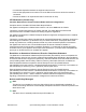
Guidance and manufacturer’s declaration – electromagnetic immunity 70 % Ut 70 % Ut Power frequency (50/60 Hz) magnetic field (30 % dip in Ut) (30 % dip in Ut) for 25 cycles for 25 cycles <5 % Ut <5 % Ut (>95 % dip in Ut) (>95 % dip in Ut) for 5 s for 5 s 3 A/m 3 A/m IEC 61000-4-8 Power frequency magnetic fields should be at levels characteristic of a typical location in a typical commercial or hospital environment. NOTE Ut is the a.c. mains voltage prior to application of the test level.
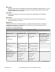
Guidance and manufacturer’s declaration – electromagnetic immunity transmitter in watts (W) according to the transmitter manufacturer and d is the recommended separation distance in metres (m). Field strengths from fixed RF transmitters, as determined by an electromagnetic site surveya, should be less than the compliance level in each frequency rangeb. Interference may occur in the vicinity of equipment marked with the following symbol: NOTE 1 At 80 MHz and 800 MHz, the higher frequency range applies.
Recommended separation distances between portable and mobile RF communication equipment and the ONA 1101GT Rated maximum output power of transmitter Separation distance according to frequency of transmitter m W 150 kHz to 80 MHz 80 MHz to 800 MHz 800 MHz to 2.5 GHz d = 1.17* √P d = 1.17* √P d = 2.33* √P 0.01 0.12 0.12 0.23 0.1 0.37 0.37 0.74 1 1.17 1.17 2.33 10 3.7 3.7 7.37 100 11.7 11.7 23.
Regulatory label for Brazil Starting the ONA There are two ways to power the ONA, but you CANNOT use both ways at the same time: • Connect a cable from a POE, POE+, or uPOE port on an Ethernet switch to the RJ-45 port with the cloud symbol on the ONA. • Use the optional external power adapter. This adapter can supply power to the ONA if there is no PoE port available or, as a backup, if the PoE port fails.
Note: The Status LED flashes slow blinking blue as the ONA starts diagnostic tests. If you did not start any tests, the ONA bypasses the Diagnostics and slow blinks amber during boot up. This is normal and does not indicate any error. Connecting the ONA to the network Procedure 1. Use a QR code reader application to get information about your ONA. The following is a sample of the information in the QR code. QR code information is subject to change.
3. If PoE power is unavailable, connect the wall unit power adapter into the DC socket to provide direct power. The 10W 100–240 AC power adapter is sold separately and comes with four snap-in plug adapters: Type A (U.S. and Japan), Type B (EU), Type G (UK), and Type I (AUS and China). The part number is EC1105E11-E6. 4. (Optional) The ONA comes with zip ties that you can use to mount the ONA near the wall unit power adapter, the device connected to the ONA, or any location you desire.
• Management IP Subnet Mask : • Default Gateway IP Address : • Primary DNS Server IP Address : • Secondary DNS Server IP Address : • DNS Domain Name : • SDN Controller IP Address or Name : • Syslog Server IP Address : • Operational Mode : 0 • Password : Note: All the fields are empty except the Operational Mode, which is 0 for the SDN Controller Mode. Use the following procedure if you want to reset the ONA to the factory default parameters: Procedure 1.
ONA can be configured with a Management IP address using DHCP.
5. On the PC, use a browser to connect to the ONA configuration menu with the address http:// 192.168.100.1. 6. Click Edit Parameters. 7. Modify the configuration parameters that you want to change. 8. Click "Save" to store the parameters in persistent memory. 9. Click "Return to Configuration page." 10. Click "Reboot into Operational Mode." 11. Disconnect the PC. System Status LED The System Status LED is visible from either side of the unit.
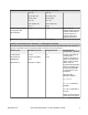
Color and Status Description SDN Controller mode status (in Mode 0 only) Red (fast blinking) Failure to obtain time of day from NTP server, rebooting in 5 seconds.
Label Color and Status Description Blue (blinking) ONA is starting Off Not operational 10/100/1000 RJ-45 Port LEDs The RJ-45 ports on both the Network side and Device side of the ONA have two bi-colored (amber/ green) LEDs. The one on the left side indicates the port speed and the one on the right side shows the level of link activity.
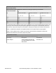
Before you begin Ensure the ONA is in Mode 0. Diagnostics only run in Mode 0. Procedure 1. Disconnect the ONA from the network switch and any device it may be attached to. 2. Use an Ethernet cable to connect the ONA Device port to its Network port, as a loopback is required to run diagnostics. 3. Connect the ONA to an external power adapter. 4. Watch the Status LED. a. Slow blinking Amber indicates the ONA is booting. b. Slow blinking Blue indicates that the diagnostics started. 5.
Note: Make sure the PC’s network port is enabled with DHCP client. 3. Insert a paper clip into the reset switch. Press and hold the reset button before applying power to the ONA. 4. Connect the cable from the network switch to the Network side of the ONA for PoE power. If PoE power is unavailable, connect an external power adapter. 5. Continue pressing and holding the reset button until the Status LED cycles through a steady red/green/blue.