
Design Reference
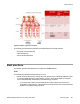

Table Of Contents
- Contents
- Chapter 1: Introduction
- Chapter 2: New in this release
- Chapter 3: Network design fundamentals
- Chapter 4: Hardware fundamentals and guidelines
- Chapter 5: Optical routing design
- Chapter 6: Platform redundancy
- Chapter 7: Link redundancy
- Chapter 8: Layer 2 loop prevention
- Chapter 9: Spanning tree
- Chapter 10: Layer 3 network design
- Chapter 11: SPBM design guidelines
- Chapter 12: IP multicast network design
- Multicast and VRF-lite
- Multicast and MultiLink Trunking considerations
- Multicast scalability design rules
- IP multicast address range restrictions
- Multicast MAC address mapping considerations
- Dynamic multicast configuration changes
- IGMPv3 backward compatibility
- IGMP Layer 2 Querier
- TTL in IP multicast packets
- Multicast MAC filtering
- Guidelines for multicast access policies
- Multicast for multimedia
- Chapter 13: System and network stability and security
- Chapter 14: QoS design guidelines
- Chapter 15: Layer 1, 2, and 3 design examples
- Chapter 16: Software scaling capabilities
- Chapter 17: Supported standards, RFCs, and MIBs
- Glossary

Important:
You must configure the MIP at the same level as the Maintenance Association
Endpoints (MEP) on all switches in the SPBM network.
Example of a configuration using best practices
spbm-id : 1
BVID #1 & BVID #2 : 4040, 4041 (ignore warning message when configuring)
nick-name : b:b0:<node-id>
MEP-id : md.ma.<node-id>
BMAC : 00:bb:00:00:<node-id>:00
VirtBMAC : 00:bb:00:00:<node-id>:ff
MD : spbm (level 4)
MA : 4040 & 4041
mep : <node-id>
mip : (level 4)
isis manual area : 49.0001
SPBM restrictions and limitations
This section describes the restrictions and limitations associated with SPBM on Avaya Virtual
Services Platform 4000.
RSTP and MSTP
The following list identifies restrictions and limitations associated with RSTP and MSTP:
• RSTP mode does not support SPBM.
• Since we support non-SPBM C-VLANs to also span the SPBM network, MSTP can be
provisioned in the network to provide loop-free connectivity for these non-SPBM C-
VLANs. Since all ports on the VSP 4000 system including IS-IS enabled NNI ports belong
to MSTP instance 0, Avaya recommends provisioning the non-SPBM C-VLANs in an
MSTP instance other than 0.
• SPBM NNI ports are not part of the Layer 2 VSN C-VLAN, and BPDUs are not transmitted
over the SPBM tunnel. SPBM can only guarantee loop-free topologies consisting of the
NNI ports. Avaya recommends that you always use Simple Loop Prevention Protocol
(SLPP) for loop prevention.
Note:
Avaya recommends that you deploy SLPP on C-VLANs to detect loops created by
customers in their access networks. However, SLPP is not required on B-VLANs, and
it is not supported. The B-VLAN active topology is controlled by IS-IS that has loop
mitigation and prevention capabilities built into the protocol.
• SPB internally uses spanning tree group (STG) 63 or Multiple Spanning Tree Instance
(MSTI) 62. STG 63 or MSTI 62 cannot be used by another VLAN or MSTI. For non-SPB
SPBM restrictions and limitations
Network Design Reference for Avaya VSP 4000 February 2014 103