
Design Reference
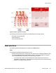

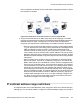
Table Of Contents
- Contents
- Chapter 1: Introduction
- Chapter 2: New in this release
- Chapter 3: Network design fundamentals
- Chapter 4: Hardware fundamentals and guidelines
- Chapter 5: Optical routing design
- Chapter 6: Platform redundancy
- Chapter 7: Link redundancy
- Chapter 8: Layer 2 loop prevention
- Chapter 9: Spanning tree
- Chapter 10: Layer 3 network design
- Chapter 11: SPBM design guidelines
- Chapter 12: IP multicast network design
- Multicast and VRF-lite
- Multicast and MultiLink Trunking considerations
- Multicast scalability design rules
- IP multicast address range restrictions
- Multicast MAC address mapping considerations
- Dynamic multicast configuration changes
- IGMPv3 backward compatibility
- IGMP Layer 2 Querier
- TTL in IP multicast packets
- Multicast MAC filtering
- Guidelines for multicast access policies
- Multicast for multimedia
- Chapter 13: System and network stability and security
- Chapter 14: QoS design guidelines
- Chapter 15: Layer 1, 2, and 3 design examples
- Chapter 16: Software scaling capabilities
- Chapter 17: Supported standards, RFCs, and MIBs
- Glossary

Multicast flow distribution over MLT
MultiLink Trunking (MLT) distributes multicast streams over a multilink trunk based on the
source MAC address and the destination MAC address. As a result, the load is distributed on
different ports of the MLT more evenly. This functionality is enabled by default on the VSP
4000 and cannot be manually configured.
Multicast scalability design rules
The following section lists the design rules to increase multicast route scaling.
Important:
The current release of the VSP 4000 does not support the following:
• PIM
• SMLT and RSMLT
• High Availability (HA)
Multicast scalability design rules
1. Whenever possible, use simple network designs that do not use VLANs that span
several switches. Instead, use routed links to connect switches.
2. Whenever possible, group sources sending to the same group in the same subnet.
Virtual Services Platform 4000 uses a single egress forwarding pointer for all
sources in the same subnet sending to the same group. Be aware that these
streams have separate hardware forwarding records on the ingress side.
3. Do not configure multicast routing on edge switch interfaces that do not contain
multicast senders or receivers. By following this rule, you:
• Provide secure control over multicast traffic that enters or exits the interface.
• Reduce the load on the switch, as well as the number of routes. This improves
overall performance and scalability.
4. Avoid initializing many (several hundred) multicast streams simultaneously. Initial
stream setup is a resource-intensive task, and initializing a large number can
increase the setup time. In some cases, this delay can result in stream loss.
5. Whenever possible, do not connect IP multicast sources and receivers by using
VLANs that interconnect switches (see the following figure). In some cases, this can
result in excessive hardware record use. By placing the source on the
interconnected VLAN, traffic takes two paths to the destination, depending on the
RPF checks and the shortest path to the source.
For example, if a receiver is on VLAN 1 on switch S1 and another receiver is on
VLAN 2 on switch S1, traffic can be received from two different paths to the two
receivers, which results in the use of two forwarding records. If the source on switch
IP multicast network design
108 Network Design Reference for Avaya VSP 4000 February 2014
Comments? infodev@avaya.com