
Design Reference
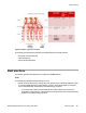

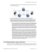
Table Of Contents
- Contents
- Chapter 1: Introduction
- Chapter 2: New in this release
- Chapter 3: Network design fundamentals
- Chapter 4: Hardware fundamentals and guidelines
- Chapter 5: Optical routing design
- Chapter 6: Platform redundancy
- Chapter 7: Link redundancy
- Chapter 8: Layer 2 loop prevention
- Chapter 9: Spanning tree
- Chapter 10: Layer 3 network design
- Chapter 11: SPBM design guidelines
- Chapter 12: IP multicast network design
- Multicast and VRF-lite
- Multicast and MultiLink Trunking considerations
- Multicast scalability design rules
- IP multicast address range restrictions
- Multicast MAC address mapping considerations
- Dynamic multicast configuration changes
- IGMPv3 backward compatibility
- IGMP Layer 2 Querier
- TTL in IP multicast packets
- Multicast MAC filtering
- Guidelines for multicast access policies
- Multicast for multimedia
- Chapter 13: System and network stability and security
- Chapter 14: QoS design guidelines
- Chapter 15: Layer 1, 2, and 3 design examples
- Chapter 16: Software scaling capabilities
- Chapter 17: Supported standards, RFCs, and MIBs
- Glossary

S2 is on a different VLAN than VLAN 3, traffic takes a single path to switch S1 where
the receivers are located.
Figure 52: IP multicast sources and receivers on interconnected VLANs
6. Avaya recommends the use of Static group-range-to-RP mappings in an SMLT
topology as opposed to RP set learning via the Bootstrap Router (BSR) mechanism.
Static RP allows for faster convergence in box failure, reset, and HA failover
scenarios; whereas there are inherent delays in the BSR mechanism as follows:
• When a router comes back up after a failover or reset, to accept and propagate
(*,g) Join requests from surrounding routers (either PIM Join messages or local
IGMP membership reports) to the RP, a PIM router must determine the
address of the RP for each group for which they desire (*,g) state. The PIM
router needs to know the unicast route to the RP address. The route to the RP
address is learned by using a unicast routing protocol such as OSPF, and the
RP address is either statically configured or dynamically learned using the BSR
mechanism.
• When a system comes up after a reset or the standby CP becomes master
after an HA failover, if the RP is not statically configured, it must wait for the
BSR to select the RP from candidate RP routers, and then propagate the RP
set hop-by-hop to all PIM routers. This must be done before a Join message
can be processed. If the PIM router receives a Join message before it learns
the RP set, the router drops the Join message and waits for another Join or
Prune message to arrive before it creates the multicast router, and propagates
the Join messages to the RP. The default Join/Prune timer is 60 seconds, and
because of this and the delays inherent in BSR RP-set learning, significant
multicast traffic interruptions can occur. If the RP is statically configured, the
only delay is in the unicast routing table convergence and the arrival of the
Join/Prune messages from surrounding boxes.
IP multicast address range restrictions
IP multicast routers use D class addresses, which range from 224.0.0.0 to 239.255.255.255.
Although you can use subnet masks to configure IP multicast address ranges, the concept of
IP multicast address range restrictions
Network Design Reference for Avaya VSP 4000 February 2014 109