
Design Reference
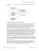

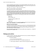
Table Of Contents
- Contents
- Chapter 1: Introduction
- Chapter 2: New in this release
- Chapter 3: Network design fundamentals
- Chapter 4: Hardware fundamentals and guidelines
- Chapter 5: Optical routing design
- Chapter 6: Platform redundancy
- Chapter 7: Link redundancy
- Chapter 8: Layer 2 loop prevention
- Chapter 9: Spanning tree
- Chapter 10: Layer 3 network design
- Chapter 11: SPBM design guidelines
- Chapter 12: IP multicast network design
- Multicast and VRF-lite
- Multicast and MultiLink Trunking considerations
- Multicast scalability design rules
- IP multicast address range restrictions
- Multicast MAC address mapping considerations
- Dynamic multicast configuration changes
- IGMPv3 backward compatibility
- IGMP Layer 2 Querier
- TTL in IP multicast packets
- Multicast MAC filtering
- Guidelines for multicast access policies
- Multicast for multimedia
- Chapter 13: System and network stability and security
- Chapter 14: QoS design guidelines
- Chapter 15: Layer 1, 2, and 3 design examples
- Chapter 16: Software scaling capabilities
- Chapter 17: Supported standards, RFCs, and MIBs
- Glossary

225.129.1.1, 239.1.1.1, 239.129.1.1 map to the same 01:00:5E:01:01:01 multicast MAC
address.
Figure 53: Multicast IP address to MAC address mapping
Most Ethernet switches handle Ethernet multicast by mapping a multicast MAC address to
multiple switch ports in the MAC address table. Therefore, when you design the group
addresses for multicast applications, take care to efficiently distribute streams only to hosts
that are receivers. Virtual Services Platform 4000 switches IP multicast data based on the IP
multicast address, not the MAC address, and thus, does not have this issue.
As an example, consider two active multicast streams using addresses 239.1.1.1 and
239.129.1.1. Suppose that two Ethernet hosts, receiver A and receiver B, connect to ports on
the same switch and only want the stream addressed to 239.1.1.1. Suppose also that two other
Ethernet hosts, receiver C and receiver D, also connect to the ports on the same switch as
receiver A and B, and want to receive the stream addressed to 239.129.1.1. If the switch uses
the Ethernet multicast MAC address to make forwarding decisions, then all four receivers
receive both streams—even though each host only wants one stream. This transmission
increases the load on both the hosts and the switch. To avoid this extra load, Avaya
recommends that you manage the IP multicast group addresses used on the network.
Virtual Services Platform 4000 does not forward IP multicast packets based on multicast MAC
addresses—even when bridging VLANs at Layer 2. Thus, the platform does not encounter this
problem. Instead, the platform internally maps IP multicast group addresses to the ports that
contain group members.
When an IP multicast packet is received, the lookup is based on the IP group address,
regardless of whether the VLAN is bridged or routed. While Virtual Services Platform 4000
does not suffer from the problem described in the previous example, other switches in the
network can. This problem is particularly true of pure Layer 2 switches.
Multicast MAC address mapping considerations
Network Design Reference for Avaya VSP 4000 February 2014 111