
Design Reference
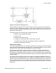
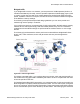

Table Of Contents
- Contents
- Chapter 1: Introduction
- Chapter 2: New in this release
- Chapter 3: Network design fundamentals
- Chapter 4: Hardware fundamentals and guidelines
- Chapter 5: Optical routing design
- Chapter 6: Platform redundancy
- Chapter 7: Link redundancy
- Chapter 8: Layer 2 loop prevention
- Chapter 9: Spanning tree
- Chapter 10: Layer 3 network design
- Chapter 11: SPBM design guidelines
- Chapter 12: IP multicast network design
- Multicast and VRF-lite
- Multicast and MultiLink Trunking considerations
- Multicast scalability design rules
- IP multicast address range restrictions
- Multicast MAC address mapping considerations
- Dynamic multicast configuration changes
- IGMPv3 backward compatibility
- IGMP Layer 2 Querier
- TTL in IP multicast packets
- Multicast MAC filtering
- Guidelines for multicast access policies
- Multicast for multimedia
- Chapter 13: System and network stability and security
- Chapter 14: QoS design guidelines
- Chapter 15: Layer 1, 2, and 3 design examples
- Chapter 16: Software scaling capabilities
- Chapter 17: Supported standards, RFCs, and MIBs
- Glossary

Figure 57: Filter decision-making process
Configure filters through the use of Access Control Lists (ACL) and Access Control Entries
(ACE), which are implemented in hardware. An ACL can include both security and QoS type
ACEs. The platform supports 2048 ACLs and 1000 ACEs for each ACL to a maximum of 16
000 ACEs for each plaform.
The following steps summarize the filter configuration process:
1. Determine your desired match fields.
2. Create an ACL.
3. Create an ACE within the ACL.
4. Configure the desired precedence, traffic type, and action.
You determine the traffic type by creating an ingress or egress ACL.
5. Modify the parameters for the ACE.
Policing and shaping
As part of the filtering process, you can police ingress traffic. Policing is performed according
to the traffic filter profile assigned to the traffic flow. For enterprise networks, policing ensures
that traffic flows conform to the criteria assigned by network managers.
Traffic policers identify traffic using a traffic policy. Traffic that conforms to this policy is
guaranteed for transmission, whereas nonconforming traffic is considered to be in violation.
Traffic policers drop packets if traffic is excessive, or remark the DSCP or 802.1p markings by
using filter actions. With Virtual Services Platform 4000, you can define multiple actions in case
of traffic violation.
For service providers, policing at the network edge provides different bandwidth options as
part of a Service Level Agreement (SLA). For example, in an enterprise network, you can police
the traffic rate from one department to give critical traffic unlimited access to the network. In a
service provider network, you can control the amount of traffic customers send to ensure that
they comply with their SLA. Policing ensures that users do not exceed their traffic contract for
a QoS level.
QoS mechanisms
Network Design Reference for Avaya VSP 4000 February 2014 131