
Design Reference
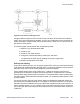
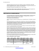
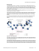
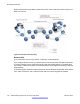
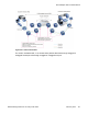

Table Of Contents
- Contents
- Chapter 1: Introduction
- Chapter 2: New in this release
- Chapter 3: Network design fundamentals
- Chapter 4: Hardware fundamentals and guidelines
- Chapter 5: Optical routing design
- Chapter 6: Platform redundancy
- Chapter 7: Link redundancy
- Chapter 8: Layer 2 loop prevention
- Chapter 9: Spanning tree
- Chapter 10: Layer 3 network design
- Chapter 11: SPBM design guidelines
- Chapter 12: IP multicast network design
- Multicast and VRF-lite
- Multicast and MultiLink Trunking considerations
- Multicast scalability design rules
- IP multicast address range restrictions
- Multicast MAC address mapping considerations
- Dynamic multicast configuration changes
- IGMPv3 backward compatibility
- IGMP Layer 2 Querier
- TTL in IP multicast packets
- Multicast MAC filtering
- Guidelines for multicast access policies
- Multicast for multimedia
- Chapter 13: System and network stability and security
- Chapter 14: QoS design guidelines
- Chapter 15: Layer 1, 2, and 3 design examples
- Chapter 16: Software scaling capabilities
- Chapter 17: Supported standards, RFCs, and MIBs
- Glossary

Enable
DiffServ
Access
DiffServ
802.1p
Override
Routed
Packet
Tagged
Ingress
Packet
Internal
QoS
Derived
From
Egress
Packet
DSCP
Derived
from
Egress
Packet
802.1p
Derived
from
1 0, L3T=1 0, L2T=1 0 1 .1p Stays
untouched
iQoS
1 0, L3T=1 0, L2T=1 X 0 DCSP Stays
untouched
iQoS
1 1, L3T=0 0, L2T=1 X 1 .1p iQoS iQoS
1 1, L3T=0 0, L2T=1 X 0 Port
QoS
iQoS iQoS
0 X, L3T=0 0, L2T=1 X 1 .1p Stays
untouched
iQoS
0 X, L3T=0 0, L2T=1 X 0 Port
QoS
Stays
untouched
iQoS
1 0, L3T=1 1, L2T=0 X X DSCP Stays
untouched
iQoS
1 1, L3T=0 1, L2T=0 X X Port
QoS
iQoS iQoS
Bridged and routed traffic
In a service provider network, access nodes use Virtual Services Platform 4000 for bridging.
In this case, Virtual Services Platform 4000 uses DiffServ to manage network traffic and
resources, but some QoS features are unavailable in the bridging mode of operation.
In an enterprise network, access nodes use Virtual Services Platform 4000 for bridging, and
core nodes use it for routing. For bridging, ingress traffic is mapped from the 802.1p-bit marking
to a QoS level. For routing, ingress traffic is mapped from the DSCP marking to the appropriate
QoS level.
802.1p and 802.1Q recommendations
In a network, to map the 802.1p user priority bits, use 802.1Q-tagged encapsulation on
customer premises equipment (CPE). You require encapsulation because Virtual Services
Platform 4000 does not provide classification when it operates in bridging mode.
To ensure consistent Layer 2 QoS boundaries within the service provider network, you must
use 802.1Q encapsulation to connect a CPE directly to Virtual Services Platform 4000 access
node. If you do not require packet classification, use Ethernet Routing Switch 5600 to connect
to the access node. In this case, configure the traffic classification functions in the Ethernet
Routing Switch 5600.
At the egress access node, packets are examined to determine if their IEEE 802.1p or DSCP
values must be re-marked before leaving the network. Upon examination, if the packet is a
tagged packet, the IEEE 802.1p tag is configured based on the QoS level-to-IEEE 802.1p-bit
mapping. For bridged packets, the DSCP is re-marked based on the QoS level.
QoS interface considerations
Network Design Reference for Avaya VSP 4000 February 2014 133