
Design Reference
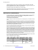
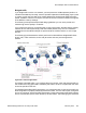
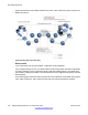
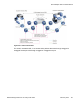

Table Of Contents
- Contents
- Chapter 1: Introduction
- Chapter 2: New in this release
- Chapter 3: Network design fundamentals
- Chapter 4: Hardware fundamentals and guidelines
- Chapter 5: Optical routing design
- Chapter 6: Platform redundancy
- Chapter 7: Link redundancy
- Chapter 8: Layer 2 loop prevention
- Chapter 9: Spanning tree
- Chapter 10: Layer 3 network design
- Chapter 11: SPBM design guidelines
- Chapter 12: IP multicast network design
- Multicast and VRF-lite
- Multicast and MultiLink Trunking considerations
- Multicast scalability design rules
- IP multicast address range restrictions
- Multicast MAC address mapping considerations
- Dynamic multicast configuration changes
- IGMPv3 backward compatibility
- IGMP Layer 2 Querier
- TTL in IP multicast packets
- Multicast MAC filtering
- Guidelines for multicast access policies
- Multicast for multimedia
- Chapter 13: System and network stability and security
- Chapter 14: QoS design guidelines
- Chapter 15: Layer 1, 2, and 3 design examples
- Chapter 16: Software scaling capabilities
- Chapter 17: Supported standards, RFCs, and MIBs
- Glossary

Bridged traffic
If you bridge traffic over the core network, you keep customer VLANs separate (similar to a
Virtual Private Network). Normally, a service provider implements VLAN bridging (Layer 2) and
no routing. In this case, the 802.1p-bit marking determines the QoS level assigned to each
packet. If DiffServ is active on core ports, the level of service received is based on the highest
of the DiffServ or 802.1p settings.
The following cases provide sample QoS design guidelines you can use to provide and
maintain high service quality in a network.
If you configure a core port, you assume that, for all incoming traffic, the QoS value is properly
marked. All core switch ports simply read and forward packets; they are not re-marked or
reclassifiied. All initial QoS markings are performed at the customer device or on the edge
devices.
The following figure illustrates the actions performed on three different bridged traffic flows
(that is VoIP, video conference, and e-mail) at access and core ports throughout the
network.
Figure 58: Trusted bridged traffic
For bridged, untrusted traffic, if you configure the port to access, mark and prioritize traffic on
the access node using global filters. Reclassify the traffic to ensure it complies with the class
of service specified in the SLA.
For Resilient Packet Ring (RPR) interworking, you can assume that, for all incoming traffic, the
QoS configuration is properly marked by the access nodes. The core switch ports, configured
as core or trunk ports, perform the RPR interworking. These ports preserve the DSCP marking
and re-mark the 802.1p bit to match the 802.1p bit of the RPR. The following figure shows the
QoS examples and recommendations
Network Design Reference for Avaya VSP 4000 February 2014 135