
Design Reference


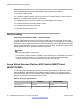
Table Of Contents
- Contents
- Chapter 1: Introduction
- Chapter 2: New in this release
- Chapter 3: Network design fundamentals
- Chapter 4: Hardware fundamentals and guidelines
- Chapter 5: Optical routing design
- Chapter 6: Platform redundancy
- Chapter 7: Link redundancy
- Chapter 8: Layer 2 loop prevention
- Chapter 9: Spanning tree
- Chapter 10: Layer 3 network design
- Chapter 11: SPBM design guidelines
- Chapter 12: IP multicast network design
- Multicast and VRF-lite
- Multicast and MultiLink Trunking considerations
- Multicast scalability design rules
- IP multicast address range restrictions
- Multicast MAC address mapping considerations
- Dynamic multicast configuration changes
- IGMPv3 backward compatibility
- IGMP Layer 2 Querier
- TTL in IP multicast packets
- Multicast MAC filtering
- Guidelines for multicast access policies
- Multicast for multimedia
- Chapter 13: System and network stability and security
- Chapter 14: QoS design guidelines
- Chapter 15: Layer 1, 2, and 3 design examples
- Chapter 16: Software scaling capabilities
- Chapter 17: Supported standards, RFCs, and MIBs
- Glossary

*Note: The seventh character (?) of the switch order number must be replaced with the proper
letter to indicate desired product nationalization. See the following for details:
“A”: No power cord included.
“B”: Includes European “Schuko” power cord common in Austria, Belgium, Finland, France,
Germany, The Netherlands, Norway, and Sweden.
“C”: Includes power cord commonly used in the United Kingdom and Ireland.
“D”: Includes power cord commonly used in Japan.
“E”: Includes North American power cord.
“F”: Includes Australian power cord.
Device cooling
Virtual Services Platform 4000 — device cooling
The VSP 4000 platform has an in-built cooling module that is not removable. Each cooling
module includes four fans providing cooling from front-to-back. There are three 12–volts fans
to maintain optimal operating temperature inside the box. The fans are also speed controlled,
based on the temperature in the box in order to minimize fan noise. Temperature sensors allow
the fan speed controller to properly support the entire unit.
Caution:
Risk of electromagnetic interference:
This device is a Class A product. Operation of this equipment in a residential area is likely
to cause harmful interference, in which case users are required to take appropriate
measures necessary to correct the interference at their own expense.
Avaya Virtual Services Platform 4000 Switch 4850GTS and
4850GTS-PWR+
The following table describes the regulatory AC power specifications for the Avaya Virtual
Services Platform 4000 4850GTS and 4850GTS-PWR+ switches. The regulatory power
specifications are based on the maximum rated capacity of the power supplies and are not
based on typical power consumption which is lower.
Table 2: AC power specifications
4850GTS 4850GTS-PWR+
Input Current: 5A/2.5A 12A/6A
Input Voltage (rms): 100 to 240VAC at 50 to 60 Hz 100 to 240VAC at 50 to 60 Hz
Hardware fundamentals and guidelines
20 Network Design Reference for Avaya VSP 4000 February 2014
Comments? infodev@avaya.com