
Design Reference
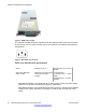
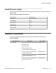
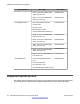
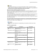
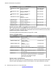

Table Of Contents
- Contents
- Chapter 1: Introduction
- Chapter 2: New in this release
- Chapter 3: Network design fundamentals
- Chapter 4: Hardware fundamentals and guidelines
- Chapter 5: Optical routing design
- Chapter 6: Platform redundancy
- Chapter 7: Link redundancy
- Chapter 8: Layer 2 loop prevention
- Chapter 9: Spanning tree
- Chapter 10: Layer 3 network design
- Chapter 11: SPBM design guidelines
- Chapter 12: IP multicast network design
- Multicast and VRF-lite
- Multicast and MultiLink Trunking considerations
- Multicast scalability design rules
- IP multicast address range restrictions
- Multicast MAC address mapping considerations
- Dynamic multicast configuration changes
- IGMPv3 backward compatibility
- IGMP Layer 2 Querier
- TTL in IP multicast packets
- Multicast MAC filtering
- Guidelines for multicast access policies
- Multicast for multimedia
- Chapter 13: System and network stability and security
- Chapter 14: QoS design guidelines
- Chapter 15: Layer 1, 2, and 3 design examples
- Chapter 16: Software scaling capabilities
- Chapter 17: Supported standards, RFCs, and MIBs
- Glossary

Caution:
Avaya recommends that you use Avaya branded SFP and SFP+ transceivers as they
undergo extensive qualification and testing. Avaya is not responsible for any problems that
arise from using non-Avaya branded SFP and SFP+ transceivers.
Small form factor (SFP) pluggable transceivers
SFPs are hot-swappable input and output enhancement components designed for use with
Avaya products to allow gigabit Ethernet ports to link with other gigabit Ethernet ports over
various media types.
You can use various SFP (1Gb/s) and SFP+ (10Gb/s) to attain different line rates and reaches.
The following table describes the SFPs including the reach provided by various SFPs.
This table is informational only—not all Avaya Ethernet switching and routing products support
all the SFPs listed here.
For more information about SFP and SFP+ transceivers, including technical specifications and
installation instructions, see Installing Transceivers and Optical components on the Avaya
Virtual Services Platform 4000, NN46251-301.
Important:
The attainable cable length can vary depending on the quality of the fiber optic cable
used.
Table 5: Compatible SFPs
Hardware
Description Part number
1000BASE-T (RJ-45)
SFP
Gigabit Ethernet, RJ-45 connector
Range up to 100 m
AA1419043-E6
1000BASE-SX (LC) DDI 850 nm, Gigabit Ethernet, duplex LC
connector
Range up to 500 m
AA1419048-E6
1000BASE-LX (LC) DDI 1310 nm, Gigabit Ethernet, duplex LC
connector
Range up to 10 km over single mode fiber
(SMF); up to 550 m over multimode fiber
(MMF)
AA1419049-E6
1000BASE-XD DDI 1310 nm, Gigabit Ethernet, duplex LC
connector
AA1419050-E6
1550 nm, Gigabit Ethernet, duplex LC
connector
AA1419051-E6
1000BASE-ZX DDI 1550 nm, Gigabit Ethernet, duplex LC
connector
AA1419052-E6
1000BASE-XD CWDM
(LC)
1470 nm to 1610 nm
Range up to 40 km
AA1419053-E6 to
AA1419060–E6
Supported optical devices
Network Design Reference for Avaya VSP 4000 February 2014 25