
Design Reference

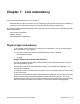
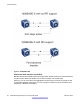
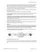
Table Of Contents
- Contents
- Chapter 1: Introduction
- Chapter 2: New in this release
- Chapter 3: Network design fundamentals
- Chapter 4: Hardware fundamentals and guidelines
- Chapter 5: Optical routing design
- Chapter 6: Platform redundancy
- Chapter 7: Link redundancy
- Chapter 8: Layer 2 loop prevention
- Chapter 9: Spanning tree
- Chapter 10: Layer 3 network design
- Chapter 11: SPBM design guidelines
- Chapter 12: IP multicast network design
- Multicast and VRF-lite
- Multicast and MultiLink Trunking considerations
- Multicast scalability design rules
- IP multicast address range restrictions
- Multicast MAC address mapping considerations
- Dynamic multicast configuration changes
- IGMPv3 backward compatibility
- IGMP Layer 2 Querier
- TTL in IP multicast packets
- Multicast MAC filtering
- Guidelines for multicast access policies
- Multicast for multimedia
- Chapter 13: System and network stability and security
- Chapter 14: QoS design guidelines
- Chapter 15: Layer 1, 2, and 3 design examples
- Chapter 16: Software scaling capabilities
- Chapter 17: Supported standards, RFCs, and MIBs
- Glossary

You can use VLACP with MLT to enhance its capabilities and provide quick failure detection.
With VLACP, the device can detect far-end failures, which permits MLT to failover properly
when end-to-end connectivity is not guaranteed for some links in an aggregation group.
To minimize network outages, you can also use VLACP to switch traffic around entire network
devices before Layer 3 protocols detect a network failure.
VLACP is an extension of the Link Aggregation Control Protocol (LACP) but LACP and VLACP
are independent features.
VLACP does not perform link aggregation, it detects end-to-end link failures.
VLACP periodically checks the end-to-end health of a point-to-point connection and it uses the
hello mechanism of LACP to periodically send hello packets to ensure end-to-end
communication.
If VLACP does not receive hello packets it transitions to a failure state, which indicates a service
provider failure, and the port is disabled. The system sends VLACP trap messages to the
management stations if the VLACP state changes. If the failure is local, the system generates
only port linkdown or port linkup traps.
VLACP works for port-to-port communications only where a guarantee exists for a logical port-
to-port match through the service provider.
VLACP does not work for port-to-multiport communications where no guarantee exists for a
point-to-point match through the service provider.
Example:
When the enterprise networks connect the aggregated Ethernet trunk groups through a service
provider network connection, far-end failures cannot be signaled with Ethernet-based functions
that operate end-to-end through the service provider network. The Multilink trunk (between
enterprise switches S1 and S2) extends through the service provider network.
The following figure shows an MLT that operates with VLACP. VLACP can operate end-to-
end, but you can also use it in a point-to-point link.
Figure 7: Problem description (1 of 2)
In the following figure, if the L2 link on S1 (S1/L2) fails, the link-down failure is not propagated
over the service provider network to S2 and S2 continues to send traffic over the failed S2/ L2
link.
Physical layer redundancy
Network Design Reference for Avaya VSP 4000 February 2014 37