
Design Reference

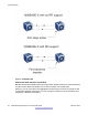
Table Of Contents
- Contents
- Chapter 1: Introduction
- Chapter 2: New in this release
- Chapter 3: Network design fundamentals
- Chapter 4: Hardware fundamentals and guidelines
- Chapter 5: Optical routing design
- Chapter 6: Platform redundancy
- Chapter 7: Link redundancy
- Chapter 8: Layer 2 loop prevention
- Chapter 9: Spanning tree
- Chapter 10: Layer 3 network design
- Chapter 11: SPBM design guidelines
- Chapter 12: IP multicast network design
- Multicast and VRF-lite
- Multicast and MultiLink Trunking considerations
- Multicast scalability design rules
- IP multicast address range restrictions
- Multicast MAC address mapping considerations
- Dynamic multicast configuration changes
- IGMPv3 backward compatibility
- IGMP Layer 2 Querier
- TTL in IP multicast packets
- Multicast MAC filtering
- Guidelines for multicast access policies
- Multicast for multimedia
- Chapter 13: System and network stability and security
- Chapter 14: QoS design guidelines
- Chapter 15: Layer 1, 2, and 3 design examples
- Chapter 16: Software scaling capabilities
- Chapter 17: Supported standards, RFCs, and MIBs
- Glossary

in the forwarding state. You can avoid this situation with consistent port level VLACP
configuration.
• Configure VLACP on an individual port basis.
The port can be either an individual port or an MLT member. Each VLACP-enabled port
periodically sends VLACP PDUs. This action allows the exchange of VLACP PDUs from
an end-to-end perspective. If a particular link does not receive VLACP PDUs, the platform
shuts the link down after the expiry timeout occurs (timeout scale x periodic time). As a
result of this action the ports stay in a disabled state.
Multilink Trunking
Use MLT to provide link layer redundancy. You can use MLT to provide alternate paths around
failed links. When you configure MLT links, consider the following information:
• The device supports 24 MLT aggregation groups.
• Up to 8 ports can belong to a single MLT group.
MLT and LACP groups and port speed
Ensure that all ports that belong to the same MLT or LACP group use the same port speed,
for example, 1 Gb/s, even if you use Auto-Negotiation. The software does not enforce this
requirement. Avaya recommends that you use Custom Auto-Negotiation Advertisement
(CANA) to ensure proper speed negotiation in mixed-port type scenarios.
To maintain Link Aggregation Group (LAG) stability during failover, use CANA: configure the
advertised speed to be the same for all LACP links. For 10/100/1000 ports, ensure that CANA
uses one particular setting, for example, 1000-full or 100-full. Otherwise, a remote device can
restart Auto-Negotiation and the link can use a different capability.
Each port must use only one speed and duplex mode; all links in Up state are guaranteed to
have the same capabilities. If you do not use Auto-Negotiation and CANA, you must use the
same speed and duplex mode settings on all ports of the MLT.
Platform-to-platform MLT link recommendations
Avaya recommends that you connect physical connections in platform-to-platform MLT and
link aggregation links in a specific order. To connect an MLT link between two platforms,
connect the lower number port on one platform with the lower number port on the other
platform. For example, to establish an MLT platform-to-platform link between ports 1/1 and 1/4
on platform A with ports 1/1 and 1/4 on platform B, do the following:
• Connect port 1/1 on platform A to port 1/1 on platform B
• Connect port 1/4 on platform A to port 1/4 on platform B
In Virtual Services Platform 4000, brouter ports do not support MLT. You cannot use brouter
ports to connect two platforms with an MLT. An alternative is to use a VLAN. This configuration
option provides a routed VLAN with a single logical port or MLT. For more information on MLT
configuration, see Avaya Virtual Services Platform 4000 Configuration — Link Aggregation
and MLT, NN46251–503.
Multilink Trunking
Network Design Reference for Avaya VSP 4000 February 2014 39