
Design Reference

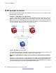
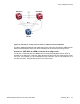
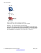
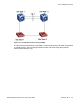

Table Of Contents
- Contents
- Chapter 1: Introduction
- Chapter 2: New in this release
- Chapter 3: Network design fundamentals
- Chapter 4: Hardware fundamentals and guidelines
- Chapter 5: Optical routing design
- Chapter 6: Platform redundancy
- Chapter 7: Link redundancy
- Chapter 8: Layer 2 loop prevention
- Chapter 9: Spanning tree
- Chapter 10: Layer 3 network design
- Chapter 11: SPBM design guidelines
- Chapter 12: IP multicast network design
- Multicast and VRF-lite
- Multicast and MultiLink Trunking considerations
- Multicast scalability design rules
- IP multicast address range restrictions
- Multicast MAC address mapping considerations
- Dynamic multicast configuration changes
- IGMPv3 backward compatibility
- IGMP Layer 2 Querier
- TTL in IP multicast packets
- Multicast MAC filtering
- Guidelines for multicast access policies
- Multicast for multimedia
- Chapter 13: System and network stability and security
- Chapter 14: QoS design guidelines
- Chapter 15: Layer 1, 2, and 3 design examples
- Chapter 16: Software scaling capabilities
- Chapter 17: Supported standards, RFCs, and MIBs
- Glossary

To enable tagging on ports that belong to a LAG, first disable LACP on the port, enable tagging
on the port, and then enable LACP.
Important:
Enabling IS-IS is not supported on LACP based MLT.
LACP and spanning tree interaction
Only the physical link state or the LACP peer status affects the operation of LACP. After a link
goes up and down, the LACP module receives notification. The spanning tree forwarding state
does not affect the operation of the LACP module. LACP data units (LACPDU) can be sent
even if the port is in spanning tree blocking state.
Configuration changes (such as speed, duplex mode, and so on) made to a LAG member port
do not apply to all the member ports of the MLT. Instead, the changed port is removed from
the LAG, and the corresponding aggregator and user is alerted.
In contrast to MLT, IEEE 802.3ad-based link aggregation does not require the system to
replicate BPDUs over all ports in the trunk group.
LACP and minimum link
The minimum link function defines the minimum number of active links required for a LAG to
remain in the forwarding state. You cannot configure the minimum link on Virtual Services
Platform 4000. The minimum link value is always 1.
If the number of active links in a LAG is 0, the entire LAG is declared down and Virtual Services
Platform 4000 informs the remote end of the LAG state by using an LACPDU.
Link aggregation group rules
Link aggregation is compatible with RSTP and MSTP. LAGs operate using the following rules:
• All ports in a LAG must operate in full-duplex mode.
• All ports in a LAG must use the same data rate.
• All ports in a LAG must be in the same VLANs.
• LAGs form using LACP.
• The platform supports a maximum of 128 LAGs.
• Each LAG supports a maximum of eight active links.
For LACP fundamentals and configuration procedures, see Avaya Virtual Services Platform
4000 Configuration — Link Aggregation and MLT NN46251-503.
802.3ad-based link aggregation
Network Design Reference for Avaya VSP 4000 February 2014 41