
Design Reference

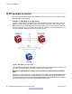
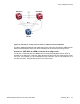
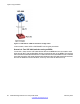
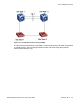

Table Of Contents
- Contents
- Chapter 1: Introduction
- Chapter 2: New in this release
- Chapter 3: Network design fundamentals
- Chapter 4: Hardware fundamentals and guidelines
- Chapter 5: Optical routing design
- Chapter 6: Platform redundancy
- Chapter 7: Link redundancy
- Chapter 8: Layer 2 loop prevention
- Chapter 9: Spanning tree
- Chapter 10: Layer 3 network design
- Chapter 11: SPBM design guidelines
- Chapter 12: IP multicast network design
- Multicast and VRF-lite
- Multicast and MultiLink Trunking considerations
- Multicast scalability design rules
- IP multicast address range restrictions
- Multicast MAC address mapping considerations
- Dynamic multicast configuration changes
- IGMPv3 backward compatibility
- IGMP Layer 2 Querier
- TTL in IP multicast packets
- Multicast MAC filtering
- Guidelines for multicast access policies
- Multicast for multimedia
- Chapter 13: System and network stability and security
- Chapter 14: QoS design guidelines
- Chapter 15: Layer 1, 2, and 3 design examples
- Chapter 16: Software scaling capabilities
- Chapter 17: Supported standards, RFCs, and MIBs
- Glossary

untagged and tagged IEEE 802.1Q VLAN link configurations. You determine to which VLANs
a switch sends SLPP test packets to. All port members of the SLPP-enabled VLAN replicate
the packets.
Use the information in this section to understand the considerations and recommendations to
configure SLPP in your network:
• You must enable SLPP packet receive on each port to detect a loop.
• SLPP test packets (SLPP-PDU) are forwarded for each VLAN.
• SLPP-PDUs are automatically forwarded on VLAN ports configured for SLPP.
• The SLPP-PDU destination MAC address is the switch MAC address, with the multicast
bit set; the source MAC address is the switch MAC address.
Note:
VSP 4000 SLPP design is different from that of ERS 8800 SLPP. On the ERS 8800,
the source MAC address is the switch VLAN MAC address.
• The SLPP-PDU is sent out as a multicast packet and is constrained to the VLAN on which
it is sent.
• If an MLT port receives an SLPP-PDU, the port goes down.
• The originating CP receives the SLPP-PDU. All other switches regard the SLPP-PDU as
a normal multicast packet, and forward it to the VLAN.
• SLPP is port-based; therefore, a port is disabled if it receives SLPP-PDU on one or more
VLANs on a tagged port. For example, if the SLPP packet receive threshold is 5, a port
is shut down if it receives 5 SLPP-PDU from one or more VLANs on a tagged port.
• The switch does not act on SLPP packets other than on the SLPP packets that it
transmits.
• For square and full-mesh configurations that use a routed core, create a separate core
VLAN. Enable SLPP on the core VLAN and the square or full-mesh links between switch
clusters. This configuration detects loops created in the core, and loops at the edge do
not affect core ports.
• You can tune network failure behavior by selecting the number of SLPP packets that must
be received before a switch takes action.
Avaya recommends the values in the following table.
Table 11: SLPP recommended values
Parameter
Configuration
Primary switch
Packet Rx threshold 5
Transmission interval 500 milliseconds (ms) (default)
Secondary switch
Packet Rx threshold 50
Layer 2 loop prevention
44 Network Design Reference for Avaya VSP 4000 February 2014
Comments? infodev@avaya.com