
Design Reference

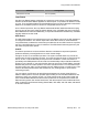
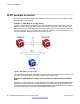
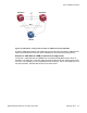
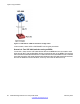
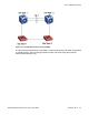

Table Of Contents
- Contents
- Chapter 1: Introduction
- Chapter 2: New in this release
- Chapter 3: Network design fundamentals
- Chapter 4: Hardware fundamentals and guidelines
- Chapter 5: Optical routing design
- Chapter 6: Platform redundancy
- Chapter 7: Link redundancy
- Chapter 8: Layer 2 loop prevention
- Chapter 9: Spanning tree
- Chapter 10: Layer 3 network design
- Chapter 11: SPBM design guidelines
- Chapter 12: IP multicast network design
- Multicast and VRF-lite
- Multicast and MultiLink Trunking considerations
- Multicast scalability design rules
- IP multicast address range restrictions
- Multicast MAC address mapping considerations
- Dynamic multicast configuration changes
- IGMPv3 backward compatibility
- IGMP Layer 2 Querier
- TTL in IP multicast packets
- Multicast MAC filtering
- Guidelines for multicast access policies
- Multicast for multimedia
- Chapter 13: System and network stability and security
- Chapter 14: QoS design guidelines
- Chapter 15: Layer 1, 2, and 3 design examples
- Chapter 16: Software scaling capabilities
- Chapter 17: Supported standards, RFCs, and MIBs
- Glossary

Figure 10: VSP 4000 as an edge router and with an additional link with ERS 8800
The SLPP PDUs generated by VSP 4000 return to the same DUT through the additional link.
After the threshold value set on the SLPP enabled ports is reached, the ports go down.
Scenario 3: VSP 4000 as a BEB connected to an edge router
In scenario 3, VSP 4000 acts as a BEB and is connected to a BayStack device. SLPP is
enabled on the UNI ports of the VSP 4000. Because the MLT ports are misconfigured, loops
can occur. For example, port 10 on BayStack is part of the MLT, but on VSP 4000 port 1/1 is
not part of the MLT, but both devices are on the same VLAN.
SLPP example scenarios
Network Design Reference for Avaya VSP 4000 February 2014 47