
Design Reference
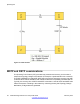

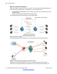
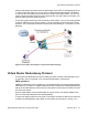
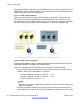
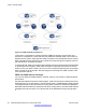
Table Of Contents
- Contents
- Chapter 1: Introduction
- Chapter 2: New in this release
- Chapter 3: Network design fundamentals
- Chapter 4: Hardware fundamentals and guidelines
- Chapter 5: Optical routing design
- Chapter 6: Platform redundancy
- Chapter 7: Link redundancy
- Chapter 8: Layer 2 loop prevention
- Chapter 9: Spanning tree
- Chapter 10: Layer 3 network design
- Chapter 11: SPBM design guidelines
- Chapter 12: IP multicast network design
- Multicast and VRF-lite
- Multicast and MultiLink Trunking considerations
- Multicast scalability design rules
- IP multicast address range restrictions
- Multicast MAC address mapping considerations
- Dynamic multicast configuration changes
- IGMPv3 backward compatibility
- IGMP Layer 2 Querier
- TTL in IP multicast packets
- Multicast MAC filtering
- Guidelines for multicast access policies
- Multicast for multimedia
- Chapter 13: System and network stability and security
- Chapter 14: QoS design guidelines
- Chapter 15: Layer 1, 2, and 3 design examples
- Chapter 16: Software scaling capabilities
- Chapter 17: Supported standards, RFCs, and MIBs
- Glossary

enable BackupMaster on the backup router, the backup router no longer switches traffic to the
VRRP Master. Instead the BackupMaster routes all traffic received on the BackupMaster IP
interface according to the switch routing table.
Figure 17: VRRP with BackupMaster
Avaya recommends that you stagger VRRP instances on a network or subnet basis. The
following figure shows the VRRP Masters and BackupMasters for two subnets. For more
information about how to configure VRRP using ACLI and Enterprise Device Manager (EDM),
see Avaya Virtual Services Platform 4000 Configuration — IP Routing, NN46251-505.
Figure 18: VRRP network configuration
The VRRP BackupMaster uses the VRRP standardized backup switch state machine. Thus,
VRRP BackupMaster is compatible with standard VRRP.
Avaya recommends that you use the following best practices to implement VRRP:
• Do not configure the virtual address as a physical interface that is used on the routing
switches. Instead, use a third address, for example:
- Interface IP address of VLAN A on Switch 1 = x.x.x.2
- Interface IP address of VLAN A on Switch 2 = x.x.x.3
- Virtual IP address of VLAN A = x.x.x.1
Note:
Avaya does not support a VRRP virtual IP address to be the same as the local physical
address of the device.
• Configure the VRRP hold down timer long enough that the Interior Gateway Protocol
(IGP) routing protocol has time to converge and update the routing table. In some cases,
Layer 3 network design
58 Network Design Reference for Avaya VSP 4000 February 2014
Comments? infodev@avaya.com