
Design Reference
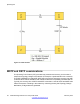
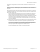

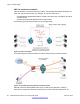
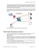
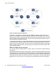
Table Of Contents
- Contents
- Chapter 1: Introduction
- Chapter 2: New in this release
- Chapter 3: Network design fundamentals
- Chapter 4: Hardware fundamentals and guidelines
- Chapter 5: Optical routing design
- Chapter 6: Platform redundancy
- Chapter 7: Link redundancy
- Chapter 8: Layer 2 loop prevention
- Chapter 9: Spanning tree
- Chapter 10: Layer 3 network design
- Chapter 11: SPBM design guidelines
- Chapter 12: IP multicast network design
- Multicast and VRF-lite
- Multicast and MultiLink Trunking considerations
- Multicast scalability design rules
- IP multicast address range restrictions
- Multicast MAC address mapping considerations
- Dynamic multicast configuration changes
- IGMPv3 backward compatibility
- IGMP Layer 2 Querier
- TTL in IP multicast packets
- Multicast MAC filtering
- Guidelines for multicast access policies
- Multicast for multimedia
- Chapter 13: System and network stability and security
- Chapter 14: QoS design guidelines
- Chapter 15: Layer 1, 2, and 3 design examples
- Chapter 16: Software scaling capabilities
- Chapter 17: Supported standards, RFCs, and MIBs
- Glossary

Figure 19: VRRP and STG configurations
In this figure, configuration A is optimal because VRRP convergence occurs within 2 to 3
seconds. In configuration A, three spanning tree instances exist and VRRP runs on the link
between the two routers. Spanning tree instance 2 exists on the link between the two routers,
which separates the link between the two routers from the spanning tree instances found on
the other devices. All uplinks are active.
In configuration B, VRRP convergence takes between 30 and 45 seconds because it depends
on spanning tree convergence. After initial convergence, spanning tree blocks one link (an
uplink), so only one uplink is used. If an error occurs on the uplink, spanning tree reconverges,
which can take up to 45 seconds. After spanning tree reconvergence, VRRP can take a few
more seconds to failover.
VRRP and ICMP redirect messages
You can use VRRP and ICMP together. However, doing so can provide nonoptimal network
performance.
Consider the network shown in the following figure. Traffic from the client on subnet 30.30.30.0,
destined for the 10.10.10.0 subnet, is sent to routing switch 1 (VRRP Master). Routing switch
1 forwards this traffic on the same subnet to routing switch 2 where it is routed to the destination.
With ICMP redirect enabled, for each packet received, routing switch 1 sends an ICMP redirect
message to the client to inform it of a shorter path to the destination through routing switch
2.
Layer 3 network design
60 Network Design Reference for Avaya VSP 4000 February 2014
Comments? infodev@avaya.com