
Design Reference
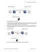
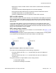
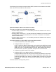
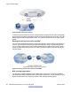
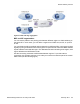
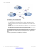
Table Of Contents
- Contents
- Chapter 1: Introduction
- Chapter 2: New in this release
- Chapter 3: Network design fundamentals
- Chapter 4: Hardware fundamentals and guidelines
- Chapter 5: Optical routing design
- Chapter 6: Platform redundancy
- Chapter 7: Link redundancy
- Chapter 8: Layer 2 loop prevention
- Chapter 9: Spanning tree
- Chapter 10: Layer 3 network design
- Chapter 11: SPBM design guidelines
- Chapter 12: IP multicast network design
- Multicast and VRF-lite
- Multicast and MultiLink Trunking considerations
- Multicast scalability design rules
- IP multicast address range restrictions
- Multicast MAC address mapping considerations
- Dynamic multicast configuration changes
- IGMPv3 backward compatibility
- IGMP Layer 2 Querier
- TTL in IP multicast packets
- Multicast MAC filtering
- Guidelines for multicast access policies
- Multicast for multimedia
- Chapter 13: System and network stability and security
- Chapter 14: QoS design guidelines
- Chapter 15: Layer 1, 2, and 3 design examples
- Chapter 16: Software scaling capabilities
- Chapter 17: Supported standards, RFCs, and MIBs
- Glossary

Open Shortest Path First
Use OSPF to ensure that the switch can communicate with other OSPF-speaking routers. This
section describes some general design considerations and presents a number of design
scenarios for OSPF.
For more information about OSPF concepts and configuration, see Avaya Virtual Services
Platform 4000 Configuration — OSPF and RIP, NN46251-506.
OSPF LSA limits
To determine OSPF link state advertisement (LSA) limits:
1. Use the command show ip ospf area to determine the LSA_CNT and to obtain
the number of LSAs for a given area.
2. Use the following formula to determine the number of areas. Ensure the total is less
than 16,000 (16K):
N = 1 to the number of areas for each switch
Adj
N
= number of adjacencies for each Area N
LSA_CNT
N
= number of LSAs for each Area N
For example, assume that a switch has a configuration of three areas with a total of 18
adjacencies and 1000 routes. This includes:
• 3 adjacencies with an LSA_CNT of 500 (Area 1)
• 10 adjacencies with an LSA_CNT of 1000 (Area 2)
• 5 adjacencies with an LSA_CNT of 200 (Area 3)
Calculate the number as follows:
3*500+10*1000+5*200=12.5K < 16K
This configuration ensures that the switch operates within accepted scalability limits.
OSPF design guidelines
Follow these additional OSPF guidelines:
• OSPF timers must be consistent across the entire network.
• Use OSPF area summarization to reduce routing table sizes.
• Use OSPF passive interfaces to reduce the number of active neighbor adjacencies.
• Use OSPF active interfaces only on intended route paths.
Configure wiring closet subnets as OSPF passive interfaces unless they form a legitimate
routing path for other routes.
Layer 3 network design
62 Network Design Reference for Avaya VSP 4000 February 2014
Comments? infodev@avaya.com