
Design Reference
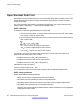
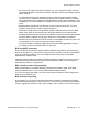
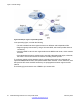
Table Of Contents
- Contents
- Chapter 1: Introduction
- Chapter 2: New in this release
- Chapter 3: Network design fundamentals
- Chapter 4: Hardware fundamentals and guidelines
- Chapter 5: Optical routing design
- Chapter 6: Platform redundancy
- Chapter 7: Link redundancy
- Chapter 8: Layer 2 loop prevention
- Chapter 9: Spanning tree
- Chapter 10: Layer 3 network design
- Chapter 11: SPBM design guidelines
- Chapter 12: IP multicast network design
- Multicast and VRF-lite
- Multicast and MultiLink Trunking considerations
- Multicast scalability design rules
- IP multicast address range restrictions
- Multicast MAC address mapping considerations
- Dynamic multicast configuration changes
- IGMPv3 backward compatibility
- IGMP Layer 2 Querier
- TTL in IP multicast packets
- Multicast MAC filtering
- Guidelines for multicast access policies
- Multicast for multimedia
- Chapter 13: System and network stability and security
- Chapter 14: QoS design guidelines
- Chapter 15: Layer 1, 2, and 3 design examples
- Chapter 16: Software scaling capabilities
- Chapter 17: Supported standards, RFCs, and MIBs
- Glossary

The following figure shows an example where OSPF operates on two subnets in two OSPF
areas. S2 becomes the ABR for both networks.
Figure 24: Example 3: OSPF on two subnets in two areas
The routers in scenario 3 use the following configuration:
• S1 has an OSPF router ID of 1.1.1.1. The OSPF port uses an IP address of 192.168.10.1,
which is in OSPF area 1.
• S2 has an OSPF router ID of 1.1.1.2. One port uses an IP address of 192.168.10.2, which
is in OSPF area 1. The second OSPF port on S2 uses an IP address of 192.168.20.1,
which is in OSPF area 2.
• S3 has an OSPF router ID of 1.1.1.3. The OSPF port uses an IP address of 192.168.20.2,
which is in OSPF area 2.
The general method to configure OSPF for this three-switch network is:
1. On all three switches, enable OSPF globally.
2. Configure OSPF on one network.
On S1, insert the IP address, subnet mask, and VLAN ID for the OSPF port. Enable
OSPF on the port. On S2, insert the IP address, subnet mask, and VLAN ID for the
OSPF port in area 1, and enable OSPF on the port. Both routable ports belong to
the same network. Therefore, by default, both ports are in the same area.
3. Configure three OSPF areas for the network.
4. Configure OSPF on two additional ports in a second subnet.
Configure additional ports and verify that IP forwarding is enabled for each switch
to ensure that routing can occur. On S2, insert the IP address, subnet mask, and
VLAN ID for the OSPF port in area 2, and enable OSPF on the port. On S3, insert
the IP address, subnet mask, and VLAN ID for the OSPF port, and enable OSPF
on the port.
The three switches exchange hello packets.
Open Shortest Path First
Network Design Reference for Avaya VSP 4000 February 2014 65