
Design Reference
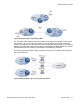


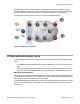


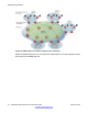
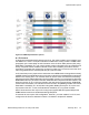

Table Of Contents
- Contents
- Chapter 1: Introduction
- Chapter 2: New in this release
- Chapter 3: Network design fundamentals
- Chapter 4: Hardware fundamentals and guidelines
- Chapter 5: Optical routing design
- Chapter 6: Platform redundancy
- Chapter 7: Link redundancy
- Chapter 8: Layer 2 loop prevention
- Chapter 9: Spanning tree
- Chapter 10: Layer 3 network design
- Chapter 11: SPBM design guidelines
- Chapter 12: IP multicast network design
- Multicast and VRF-lite
- Multicast and MultiLink Trunking considerations
- Multicast scalability design rules
- IP multicast address range restrictions
- Multicast MAC address mapping considerations
- Dynamic multicast configuration changes
- IGMPv3 backward compatibility
- IGMP Layer 2 Querier
- TTL in IP multicast packets
- Multicast MAC filtering
- Guidelines for multicast access policies
- Multicast for multimedia
- Chapter 13: System and network stability and security
- Chapter 14: QoS design guidelines
- Chapter 15: Layer 1, 2, and 3 design examples
- Chapter 16: Software scaling capabilities
- Chapter 17: Supported standards, RFCs, and MIBs
- Glossary

B-MAC
An SPBM backbone includes Backbone Edge Bridges (BEB) and Backbone Core Bridges
(BCB). A BEB performs the same functionality as a BCB, but it also terminates one or more
Virtual Service Networks (VSNs). A BCB does not terminate any VSNs and is unaware of the
VSN traffic it transports. A BCB simply knows how to reach any other BEB in the SPBM
backbone.
To forward customer traffic across the service provider backbone, the BEB for the VSN
encapsulates the customer Ethernet packet received at the edge into a Backbone MAC header
using the 802.1ah MAC-in-MAC encapsulation. This encapsulation hides the Customer MAC
(C-MAC) address in a Backbone MAC (B-MAC) address pair. MAC-in-MAC encapsulation
defines a BMAC-DA and BMAC-SA to identify the backbone source and destination addresses.
The originating node creates a MAC header for delivery from end to end. Intermediate BCB
nodes within the SPBM backbone perform packet forwarding using BMAC-DA alone. When
the packet reaches the intended egress BEB, the B-MAC header is removed and the original
customer packet is forwarded.
I-SID
SPBM introduces a service instance identifier called I-SID. SPBM uses I-SIDs to separate
services from the infrastructure. After you create an SPBM infrastructure, you can add
additional services (such as VLAN extensions or VRF extensions) by provisioning the
endpoints only. The SPBM endpoints are BEBs, which mark the boundary between the core
MAC-in-MAC SPBM domain and the edge customer 802.1Q domain. I-SIDs are provisioned
on the BEBs to be associated with a particular service instance. In the SPBM core, the bridges
are BCBs. BCBs forward encapsulated traffic based on the BMAC-DA.
The SPBM B-MAC header includes an I-SID. The length of the I–SID is 32 bits with a 24–bit
ID. I-SIDs identify and transmit virtualized traffic in an encapsulated SPBM frame. These I-
SIDs are used in a VSN for VLANs or VRFs across the MAC-in-MAC backbone:
• For a Layer 2 VSN, the I-SID is associated with a customer VLAN, which is then virtualized
across the backbone. Layer 2 VSNs offer an any-any LAN service type. Layer 2 VSNs
associate one VLAN per I-SID.
• For a Layer 2 VSN with multicast, the BEB associates a data I-SID with the multicast
stream and a scope I-SID that defines the scope as a Layer 2 VSN. A multicast stream
with a Layer 2 VSN scope can only transmit a multicast stream for the same Layer 2
VSN.
• For a Layer 3 VSN, the I-SID is associated with a customer VRF, which is also virtualized
across the backbone. Layer 3 VSNs are always full-mesh topologies. Layer 3 VSNs
associate one VRF per I-SID.
• For a Layer 3 VSN with multicast, the BEB associates a data I-SID with the multicast
stream and a scope I-SID that defines the scope as a Layer 3 VSN. A multicast stream
with a Layer 3 VSN scope can only transmit a multicast stream for the same Layer 3
VSN.
• For IP Shortcuts with multicast, the BEB associates a data I-SID with the multicast stream
and defines the scope as Layer 3 GRT. A multicast stream with a scope of Layer 3 GRT
can only transmit a multicast stream for the Layer 3 GRT.
SPBM design guidelines
74 Network Design Reference for Avaya VSP 4000 February 2014
Comments? infodev@avaya.com