
Design Reference
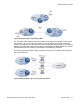

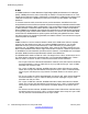
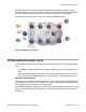
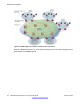
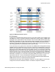
Table Of Contents
- Contents
- Chapter 1: Introduction
- Chapter 2: New in this release
- Chapter 3: Network design fundamentals
- Chapter 4: Hardware fundamentals and guidelines
- Chapter 5: Optical routing design
- Chapter 6: Platform redundancy
- Chapter 7: Link redundancy
- Chapter 8: Layer 2 loop prevention
- Chapter 9: Spanning tree
- Chapter 10: Layer 3 network design
- Chapter 11: SPBM design guidelines
- Chapter 12: IP multicast network design
- Multicast and VRF-lite
- Multicast and MultiLink Trunking considerations
- Multicast scalability design rules
- IP multicast address range restrictions
- Multicast MAC address mapping considerations
- Dynamic multicast configuration changes
- IGMPv3 backward compatibility
- IGMP Layer 2 Querier
- TTL in IP multicast packets
- Multicast MAC filtering
- Guidelines for multicast access policies
- Multicast for multimedia
- Chapter 13: System and network stability and security
- Chapter 14: QoS design guidelines
- Chapter 15: Layer 1, 2, and 3 design examples
- Chapter 16: Software scaling capabilities
- Chapter 17: Supported standards, RFCs, and MIBs
- Glossary

VSP 9000 and VSP 4000 implementation
If a VLAN is attached to an I-SID there must be another instance of that same I-SID in the
SPBM network.
• If there is another instance of that I-SID, the device designates that VLAN as operationally
up regardless of whether it has a member port or not.
When the VLAN is operationally up, the IP address of the VLAN will be in the routing
table.
• If there is NO matching instance of the I-SID in the SPBM network, then that VLAN does
not have any reachable members so it is not acting as an NNI interface.
The VLAN is also not acting as a UNI interface because it does not have a member
port.
Therefore, the device does not designate the VLAN as operationally up because the
VLAN is not acting as a UNI or an NNI interface.
If the device is just acting as a BCB with two VLANs configured and two I-SIDs, there must be
a UNI side with the corresponding I-SID existing in the network.
If the device is acting as both BEB and BCB, then there must be a member port in that VLAN
in order to push out the UNI traffic.
Provisioning
This section summarizes how to provision SPBM. For information on specific configuration
commands, see Configuring Avaya VENA Fabric Connect on Avaya Virtual Services Platform
4000, NN46251–510.
Infrastructure provisioning
Provisioning an SPBM core is as simple as enabling SPBM and IS-IS globally, and on all the
IS-IS core Ethernet links on all the BCB and BEB nodes. The IS-IS protocol operates at Layer
2 so it does not need IP addresses configured on the links to form IS-IS adjacencies with
neighboring switches (like OSPF does). You do not need to configure IP addresses on any of
the core links. The encapsulation of customer MAC addresses in backbone MAC addresses
greatly improves network scalability.
No flooding or learning of end-user MACs occurs in the backbone. This SPBM provisioning
significantly improves network robustness, as customer-introduced network loops have no
effect on the backbone infrastructure.
Service provisioning
Provision I-SIDs on a BEB to associate that BEB with a particular service instance. After you
map the customer VLAN or VRF into an I-SID, any BEB that has the same I-SID configured
SPBM design guidelines
76 Network Design Reference for Avaya VSP 4000 February 2014
Comments? infodev@avaya.com