
Design Reference
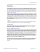


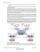

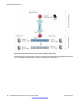
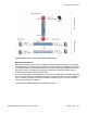

Table Of Contents
- Contents
- Chapter 1: Introduction
- Chapter 2: New in this release
- Chapter 3: Network design fundamentals
- Chapter 4: Hardware fundamentals and guidelines
- Chapter 5: Optical routing design
- Chapter 6: Platform redundancy
- Chapter 7: Link redundancy
- Chapter 8: Layer 2 loop prevention
- Chapter 9: Spanning tree
- Chapter 10: Layer 3 network design
- Chapter 11: SPBM design guidelines
- Chapter 12: IP multicast network design
- Multicast and VRF-lite
- Multicast and MultiLink Trunking considerations
- Multicast scalability design rules
- IP multicast address range restrictions
- Multicast MAC address mapping considerations
- Dynamic multicast configuration changes
- IGMPv3 backward compatibility
- IGMP Layer 2 Querier
- TTL in IP multicast packets
- Multicast MAC filtering
- Guidelines for multicast access policies
- Multicast for multimedia
- Chapter 13: System and network stability and security
- Chapter 14: QoS design guidelines
- Chapter 15: Layer 1, 2, and 3 design examples
- Chapter 16: Software scaling capabilities
- Chapter 17: Supported standards, RFCs, and MIBs
- Glossary

12 (I-SID 12990012) on the VRF instance configured. Note that for these VSNs, node VSP-G
acts as a BEB.
E—Layer 3 VSN
Layer 3 VSNs are very similar to Layer 2 VSNs. The difference between the two is that Layer
2 VSNs associate I-SIDs with VLANs. Layer 3 VSNs associate I-SIDs with VRFs. With the
Layer 3 VSN option, all VRFs in the network that share the same I-SID can participate in the
same VSN by advertising their reachable IP routes into IS-IS and installing IP routes learned
from IS-IS. Suitable IP redistribution policies need to be defined to determine what IP routes
a BEB will advertise to IS-IS.
As seen in
Figure 33: SPBM implementation options on page 79, the green VRF on VSP-C is
configured to advertise its local or direct IP routes into IS-IS within I-SID 13990001. The VRF
on node VSP-D, which is also a member of the same I-SID, installs these IP routes in its VRF
IP routing table with a next-hop B-MAC address of VSP-C. Therefore, when the VRF on node
VSP-D needs to IP route traffic to the IP subnet off VSP-C, it performs a lookup in its IP routing
table and applies a MAC-in- MAC encapsulation with B-MAC DA of VSP-C. The SPBM core
ensures delivery to the egress BEB VSP-C where the encapsulation is removed and the packet
is IP routed onwards.
Note:
Like the IP shortcut service, there are only two IP routing hops (ingress BEB and egress
BEB) as the SPBM backbone acts as a virtualized switching backplane.
F—Layer 3 VSN
Figure 33: SPBM implementation options on page 79 shows two VRFs (green and red) to
illustrate that the BEBs can associate ISIDs with multiple VRFs. The Layer 3 VSN option
provides IP connectivity over SPBM for all of your VRFs.
G—Layer 2 VSN and Layer 3 VSN
Figure 33: SPBM implementation options on page 79 shows both a Layer 2 VSN and a Layer
3 VSN to show that you can configure both options on the same BEBs. This topology is simply
made up of a number of BEBs that terminate VSNs of both types. What this example shows
is the flexibility to extend one or more edge VLANs (using one or more Layer 2 VSNs) to use
a default gateway that is deeper into the SPBM core. From here, traffic can then be IP routed
onwards as either non-virtualized with IP shortcuts or, as shown in this example, with a
virtualized Layer 3 VSN. Note that in this example the central node VSP-G is now also acting
as BEB for both service types as it now maintains both a MAC table for the Layer 2 VSN it
terminates, and an ARP cache and IP routing table for the Layer 3 VSN it also terminates.
Multiple tenants using different SPBM services
The following figure shows multiple tenants using different services within an SPBM metro
network. In this network, you can use some or all of the SPBM implementation options to meet
the needs of the community while maintaining the security of information within VLAN
members.
Implementation options
Network Design Reference for Avaya VSP 4000 February 2014 81