
Design Reference

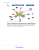


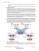

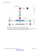

Table Of Contents
- Contents
- Chapter 1: Introduction
- Chapter 2: New in this release
- Chapter 3: Network design fundamentals
- Chapter 4: Hardware fundamentals and guidelines
- Chapter 5: Optical routing design
- Chapter 6: Platform redundancy
- Chapter 7: Link redundancy
- Chapter 8: Layer 2 loop prevention
- Chapter 9: Spanning tree
- Chapter 10: Layer 3 network design
- Chapter 11: SPBM design guidelines
- Chapter 12: IP multicast network design
- Multicast and VRF-lite
- Multicast and MultiLink Trunking considerations
- Multicast scalability design rules
- IP multicast address range restrictions
- Multicast MAC address mapping considerations
- Dynamic multicast configuration changes
- IGMPv3 backward compatibility
- IGMP Layer 2 Querier
- TTL in IP multicast packets
- Multicast MAC filtering
- Guidelines for multicast access policies
- Multicast for multimedia
- Chapter 13: System and network stability and security
- Chapter 14: QoS design guidelines
- Chapter 15: Layer 1, 2, and 3 design examples
- Chapter 16: Software scaling capabilities
- Chapter 17: Supported standards, RFCs, and MIBs
- Glossary

Figure 36: SPBM basic architecture
Provisioning an SPBM core is as simple as enabling SPBM and IS-IS globally on all the nodes
and on the core facing links. To migrate an existing edge configuration into an SPBM network
is just as simple.
The boundary between the MAC-in-MAC SPBM domain and the 802.1Q domain is handled
by the BEBs. At the BEBs, VLANs or VRFs are mapped into I-SIDs based on the local service
provisioning. Services (whether Layer 2 or Layer 3 VSNs) only need to be configured at the
edge of the SPBM backbone (on the BEBs). There is no provisioning needed on the core SPBM
nodes.
The following figure illustrates an existing edge that connects to an SPBM core.
SPBM design guidelines
84 Network Design Reference for Avaya VSP 4000 February 2014
Comments? infodev@avaya.com