
Design Reference
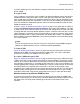
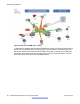


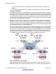

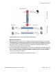

Table Of Contents
- Contents
- Chapter 1: Introduction
- Chapter 2: New in this release
- Chapter 3: Network design fundamentals
- Chapter 4: Hardware fundamentals and guidelines
- Chapter 5: Optical routing design
- Chapter 6: Platform redundancy
- Chapter 7: Link redundancy
- Chapter 8: Layer 2 loop prevention
- Chapter 9: Spanning tree
- Chapter 10: Layer 3 network design
- Chapter 11: SPBM design guidelines
- Chapter 12: IP multicast network design
- Multicast and VRF-lite
- Multicast and MultiLink Trunking considerations
- Multicast scalability design rules
- IP multicast address range restrictions
- Multicast MAC address mapping considerations
- Dynamic multicast configuration changes
- IGMPv3 backward compatibility
- IGMP Layer 2 Querier
- TTL in IP multicast packets
- Multicast MAC filtering
- Guidelines for multicast access policies
- Multicast for multimedia
- Chapter 13: System and network stability and security
- Chapter 14: QoS design guidelines
- Chapter 15: Layer 1, 2, and 3 design examples
- Chapter 16: Software scaling capabilities
- Chapter 17: Supported standards, RFCs, and MIBs
- Glossary

SID instance and then associated with either a VLAN in an Layer 2 VSN or terminated into a
VRF in an Layer 3 VSN. You can also terminate the C-VLAN into the default router, which uses
IP shortcuts to IP route over the SPBM core.
In an SPBM network design, the only nodes where it makes sense to have an SMLT cluster
configuration is on the BEB nodes where VSN services terminate. These are the SPBM nodes
where C-VLANs exist and these C-VLANs need to be redundantly extended to non-SPBM
devices such as Layer 2 edge stackable switches. On the BCB core nodes where no VSNs
are terminated and no Layer 2 edge stackables are connected, there is no longer any use for
the SMLT clustering functionality. Therefore, in the depicted SPBM design, the SMLT/IST
configuration can be removed from the core nodes because they now act as pure BCBs that
have no knowledge of the VSN they transport and the only control plane protocol they need
to run is IS-IS.
Because SMLT BEB nodes exist in this design (the edge BEBs) and it is desirable to use equal
cost paths to load balance VSN traffic across the SPBM core, all SPBM nodes in the network
are configured with the same two B-VIDs.
Where
Figure 38: SPBM campus without SMLT on page 86 shows the physical topology, the
following two figures illustrate a logical rendition of the same topology. In both of the following
figures, you can see that the core is almost identical. Because the SPBM core just serves as
a transport mechanism that transmits traffic to the destination BEB, all the provisioning is done
at the edge.
In the data center, VLANs are attached to Inter-VSNs that transmit the traffic across the SPBM
core between the data center on the left and the data center on the right. A common application
of this service is VMotion moving VMs from one data center to another.
The following figure uses IP shortcuts that route VLANs. There is no I-SID configuration and
no Layer 3 virtualization between the edge distribution and the core. This is normal IP
forwarding to the BEB.
Reference architectures
Network Design Reference for Avaya VSP 4000 February 2014 87