
Design Reference

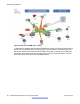


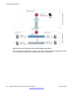

Table Of Contents
- Contents
- Chapter 1: Introduction
- Chapter 2: New in this release
- Chapter 3: Network design fundamentals
- Chapter 4: Hardware fundamentals and guidelines
- Chapter 5: Optical routing design
- Chapter 6: Platform redundancy
- Chapter 7: Link redundancy
- Chapter 8: Layer 2 loop prevention
- Chapter 9: Spanning tree
- Chapter 10: Layer 3 network design
- Chapter 11: SPBM design guidelines
- Chapter 12: IP multicast network design
- Multicast and VRF-lite
- Multicast and MultiLink Trunking considerations
- Multicast scalability design rules
- IP multicast address range restrictions
- Multicast MAC address mapping considerations
- Dynamic multicast configuration changes
- IGMPv3 backward compatibility
- IGMP Layer 2 Querier
- TTL in IP multicast packets
- Multicast MAC filtering
- Guidelines for multicast access policies
- Multicast for multimedia
- Chapter 13: System and network stability and security
- Chapter 14: QoS design guidelines
- Chapter 15: Layer 1, 2, and 3 design examples
- Chapter 16: Software scaling capabilities
- Chapter 17: Supported standards, RFCs, and MIBs
- Glossary

1. Layer 2 Virtual Services Network with IGMP support on the access networks for
optimized forwarding of IP multicast traffic in a bridged network (L2 VSN with
multicast)
2. IP multicast routing support for Global Routing Table using SPB in the core (IP
Shortcuts with multicast)
3. Layer 3 Virtual Services Network with VRF based IP multicast routing support over
SPB in the core and IGMP on the access (L3 VSN with multicast)
All multicast streams are constrained within the level in which they originate, which is called
the scope level. In other words, if a sender transmits a multicast stream to a BEB on a C-VLAN
with IP multicast over SPBM enabled, only receivers that are part of the same Layer 2 VSN
can receive that stream. Similarly, if a sender transmits a multicast stream to a BEB on a VLAN
that is part of the Layer 3 VSN with IP multicast over SPBM enabled, only receivers that are
part of the same Layer 3 instance can receive that stream.
IP multicast over SPBM uses BEBs to act as senders and receivers of data. After a BEB
receives IP multicast data from a sender, a BEB allocates a data I-SID in the range of
16,000,000 to 16,512,000 for the stream. The stream is identified by the S,G,V tuple, which is
the source IP address, group IP Address, and the stream is identified by the local VLAN on
which the stream is received. The BEB also sends a TLV update to its neighbors to inform
them of the presence of an IP multicast stream, along with identifying the sender. The BEB
propagates the information through the SPBM cloud through IS-IS TLV updates in LSPs that
result in a multicast tree being created for that stream.
IGMP handles group membership registration to enable members to receive data. IGMP
snooping listens to conversations between hosts and routers, and maintains a table of links
that require IP multicast streams.
The BEBs also act as IGMP queriers and send out periodic IGMP queries. The IGMP querier
enables the creation of the link table. After a BEB receives an IGMP join message from a
receiver, a BEB queries the IS-IS database to check if a sender exists for the requested stream
within the scope of the receiver. If the requested stream does not exist, the IGMP information
is kept, but no further action is taken. If the requested stream exists, the BEB sends an IS-IS
TLV update to its neighbors to inform them of the presence of a receiver and this information
is propagated through the SPBM cloud.
IS-IS acts dynamically using the TLV information it receives from BEBs that connect to the
sender and the receivers to create a multicast tree between them.
The following figure shows how multicast senders and receivers connect to the SPBM cloud
using BEBs.
SPBM design guidelines
90 Network Design Reference for Avaya VSP 4000 February 2014
Comments? infodev@avaya.com