
Design Reference
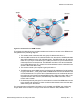
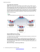
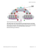
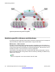
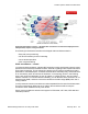
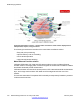
Table Of Contents
- Contents
- Chapter 1: Introduction
- Chapter 2: New in this release
- Chapter 3: Network design fundamentals
- Chapter 4: Hardware fundamentals and guidelines
- Chapter 5: Optical routing design
- Chapter 6: Platform redundancy
- Chapter 7: Link redundancy
- Chapter 8: Layer 2 loop prevention
- Chapter 9: Spanning tree
- Chapter 10: Layer 3 network design
- Chapter 11: SPBM design guidelines
- Chapter 12: IP multicast network design
- Multicast and VRF-lite
- Multicast and MultiLink Trunking considerations
- Multicast scalability design rules
- IP multicast address range restrictions
- Multicast MAC address mapping considerations
- Dynamic multicast configuration changes
- IGMPv3 backward compatibility
- IGMP Layer 2 Querier
- TTL in IP multicast packets
- Multicast MAC filtering
- Guidelines for multicast access policies
- Multicast for multimedia
- Chapter 13: System and network stability and security
- Chapter 14: QoS design guidelines
- Chapter 15: Layer 1, 2, and 3 design examples
- Chapter 16: Software scaling capabilities
- Chapter 17: Supported standards, RFCs, and MIBs
- Glossary

Large data center architecture
SPBM supports data centers with IP shortcuts, Layer 2 VSNs, or Layer 3 VSNs. If you use
vMotion, you must use Layer 2 between data centers (Layer 2 VSN). With Layer 2 VSNs, you
can add IP addresses to the VLAN on both data centers and run Virtual Router Redundancy
Protocol (VRRP) between them to allow the ESX server to route to the rest of the network.
The following figure shows an SPBM topology of a large data center. This figure represents a
full-mesh Virtual Enterprise Network Architecture (VENA) data center fabric using SPBM for
storage over Ethernet. This topology is optimized for storage transport because traffic never
travels more than two hops.
Note:
Avaya recommends that you use a two-tier, full-mesh topology for large data centers.
Figure 42: SPBM data center—full mesh
Traditional data center routing of VMs:
In a traditional data center configuration, the traffic flows into the network to a VM and out of
the network in almost a direct path.
The following figure shows an example of a traditional data center with VRRP configured.
Because end stations are often configured with a static default gateway IP address, a loss of
the default gateway router causes a loss of connectivity to the remote networks. VRRP
eliminates the single point of failure that can occur when the single static default gateway router
for an end station is lost.
Data Center Routing — Traditional (pre VM move):
SPBM design guidelines
92 Network Design Reference for Avaya VSP 4000 February 2014
Comments? infodev@avaya.com