
Design Reference
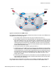
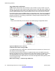
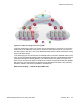
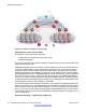
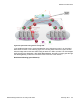
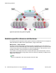
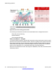
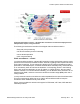
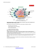
Table Of Contents
- Contents
- Chapter 1: Introduction
- Chapter 2: New in this release
- Chapter 3: Network design fundamentals
- Chapter 4: Hardware fundamentals and guidelines
- Chapter 5: Optical routing design
- Chapter 6: Platform redundancy
- Chapter 7: Link redundancy
- Chapter 8: Layer 2 loop prevention
- Chapter 9: Spanning tree
- Chapter 10: Layer 3 network design
- Chapter 11: SPBM design guidelines
- Chapter 12: IP multicast network design
- Multicast and VRF-lite
- Multicast and MultiLink Trunking considerations
- Multicast scalability design rules
- IP multicast address range restrictions
- Multicast MAC address mapping considerations
- Dynamic multicast configuration changes
- IGMPv3 backward compatibility
- IGMP Layer 2 Querier
- TTL in IP multicast packets
- Multicast MAC filtering
- Guidelines for multicast access policies
- Multicast for multimedia
- Chapter 13: System and network stability and security
- Chapter 14: QoS design guidelines
- Chapter 15: Layer 1, 2, and 3 design examples
- Chapter 16: Software scaling capabilities
- Chapter 17: Supported standards, RFCs, and MIBs
- Glossary

Figure 44: Traditional routing after moving VMs
Optimized data center routing of VMs:
Two features make a data center optimized:
• VLAN routers in the Layer 2 domain (green icons)
• VRRP BackupMaster
The VLAN routers use lookup tables to determine the best path to route incoming traffic (red
dots) to the destination VM.
VRRP BackupMaster solves the problem of traffic congestion on the IST. Because there can
be only one VRRP Master, all other interfaces are in backup mode. In this case, all traffic is
forwarded over the IST link towards the primary VRRP switch. All traffic that arrives at the
VRRP backup interface is forwarded, so there is not enough bandwidth on the IST link to carry
all the aggregated riser traffic. VRRP BackupMaster overcomes this issue by ensuring that the
IST trunk is not used in such a case for primary data forwarding. The VRRP BackupMaster
acts as an IP router for packets destined for the logical VRRP IP address. All traffic is directly
routed to the destined subnetwork and not through Layer 2 switches to the VRRP Master. This
avoids potential limitation in the available IST bandwidth.
The following figure shows a solution that optimizes your network for bidirectional traffic flows.
However, this solution turns two SPBM BCB nodes into BEBs where MAC and ARP learning
will be enabled on the Inter-VSN routing interfaces. If you do not care about top-down traffic
flows, you can omit the Inter-VSN routing interfaces on the SPBM BCB nodes. This makes the
IP routed paths top-down less optimal, but the BCBs remain pure BCBs, thus simplifying core
switch configurations.
Distributed vRouting — Optimized (pre VM move):
SPBM design guidelines
94 Network Design Reference for Avaya VSP 4000 February 2014
Comments? infodev@avaya.com