
Design Reference
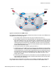
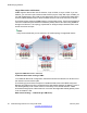
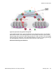
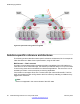
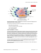
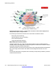
Table Of Contents
- Contents
- Chapter 1: Introduction
- Chapter 2: New in this release
- Chapter 3: Network design fundamentals
- Chapter 4: Hardware fundamentals and guidelines
- Chapter 5: Optical routing design
- Chapter 6: Platform redundancy
- Chapter 7: Link redundancy
- Chapter 8: Layer 2 loop prevention
- Chapter 9: Spanning tree
- Chapter 10: Layer 3 network design
- Chapter 11: SPBM design guidelines
- Chapter 12: IP multicast network design
- Multicast and VRF-lite
- Multicast and MultiLink Trunking considerations
- Multicast scalability design rules
- IP multicast address range restrictions
- Multicast MAC address mapping considerations
- Dynamic multicast configuration changes
- IGMPv3 backward compatibility
- IGMP Layer 2 Querier
- TTL in IP multicast packets
- Multicast MAC filtering
- Guidelines for multicast access policies
- Multicast for multimedia
- Chapter 13: System and network stability and security
- Chapter 14: QoS design guidelines
- Chapter 15: Layer 1, 2, and 3 design examples
- Chapter 16: Software scaling capabilities
- Chapter 17: Supported standards, RFCs, and MIBs
- Glossary

Figure 45: Optimized routing before moving VMs
In the traditional data center, chaos resulted after many VMs were moved. In an optimized
data center as shown in the following figure, the incoming traffic enters the Layer 2 domain
where an edge switch uses Inter-VSN routing to attach an I-SID to a VLAN. The I-SID bridges
traffic directly to the destination. With VRRP BackupMaster, the traffic no longer goes through
the default gateway; it takes the most direct route in and out of the network.
Distributed vRouting (post VM move):
Reference architectures
Network Design Reference for Avaya VSP 4000 February 2014 95