
Design Reference
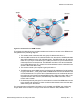
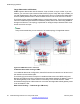
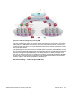
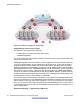
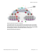
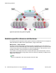
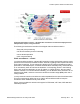
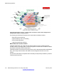
Table Of Contents
- Contents
- Chapter 1: Introduction
- Chapter 2: New in this release
- Chapter 3: Network design fundamentals
- Chapter 4: Hardware fundamentals and guidelines
- Chapter 5: Optical routing design
- Chapter 6: Platform redundancy
- Chapter 7: Link redundancy
- Chapter 8: Layer 2 loop prevention
- Chapter 9: Spanning tree
- Chapter 10: Layer 3 network design
- Chapter 11: SPBM design guidelines
- Chapter 12: IP multicast network design
- Multicast and VRF-lite
- Multicast and MultiLink Trunking considerations
- Multicast scalability design rules
- IP multicast address range restrictions
- Multicast MAC address mapping considerations
- Dynamic multicast configuration changes
- IGMPv3 backward compatibility
- IGMP Layer 2 Querier
- TTL in IP multicast packets
- Multicast MAC filtering
- Guidelines for multicast access policies
- Multicast for multimedia
- Chapter 13: System and network stability and security
- Chapter 14: QoS design guidelines
- Chapter 15: Layer 1, 2, and 3 design examples
- Chapter 16: Software scaling capabilities
- Chapter 17: Supported standards, RFCs, and MIBs
- Glossary

Figure 47: Small core — Multi-tenant
The following list outlines the benefits of the fabric connect based solution:
• end-point provisioning
• fast failover
• simple to configure
• L2 and L3 virtualized
Hosted data center management solution — ETREE
In some hosted data center solutions, the hosting center operating company takes
responsibility for managing customer servers. For this shared management, shown in the
following figure, servers that control the operating system level of the production servers, such
as the patch level, are deployed. Because customer production servers do not communicate
with each other, a distributed private VLAN solution based on fabric connect is deployed to
manage all production servers. This solution builds a distributed set of ETREEs for each
management domain.
VSP 9000, ERS 8000, VSP 7000 as core and VSP 4000 as access, provide an elegant
network-wide ETREE solution. Spokes, or managed servers, cannot communicate to each
other over this network, but the shared management servers on the hub ports can access all
spokes. Because of the L2 – ETREE nature of this setup, the managed servers do not require
any route entries, and only require one IP interface in this management private VLAN. This
solution supports tagged, untagged physical and virtual (VM) servers.
Solution-specific reference architectures
Network Design Reference for Avaya VSP 4000 February 2014 97