
Design Reference
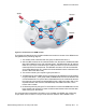
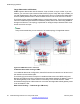
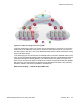
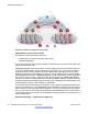
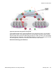
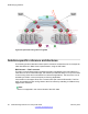
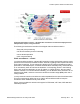
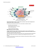
Table Of Contents
- Contents
- Chapter 1: Introduction
- Chapter 2: New in this release
- Chapter 3: Network design fundamentals
- Chapter 4: Hardware fundamentals and guidelines
- Chapter 5: Optical routing design
- Chapter 6: Platform redundancy
- Chapter 7: Link redundancy
- Chapter 8: Layer 2 loop prevention
- Chapter 9: Spanning tree
- Chapter 10: Layer 3 network design
- Chapter 11: SPBM design guidelines
- Chapter 12: IP multicast network design
- Multicast and VRF-lite
- Multicast and MultiLink Trunking considerations
- Multicast scalability design rules
- IP multicast address range restrictions
- Multicast MAC address mapping considerations
- Dynamic multicast configuration changes
- IGMPv3 backward compatibility
- IGMP Layer 2 Querier
- TTL in IP multicast packets
- Multicast MAC filtering
- Guidelines for multicast access policies
- Multicast for multimedia
- Chapter 13: System and network stability and security
- Chapter 14: QoS design guidelines
- Chapter 15: Layer 1, 2, and 3 design examples
- Chapter 16: Software scaling capabilities
- Chapter 17: Supported standards, RFCs, and MIBs
- Glossary

Figure 49: Deployment scenario — Bridged video surveillance and IP camera deployment for
transportation, airports, and government
The following list outlines the benefits of the bridged video surveillance solution:
• Easy end-point provisioning
• sub second resiliency and mc forwarding
• secure tenant separation
• quick camera switching
Video surveillance — routed
In a video surveillance solution, optimal traffic forwarding is a key requirement to ensure proper
operation of the camera and recorder solutions. However, signaling is also important to ensure
quick channel switching. This is achieved by deploying an IP multicast infrastructure that is
optimized for multicast transport, so that the cameras can be selected quickly, and so that there
is no unnecessary traffic sent across the backbone. In the topology shown in the following
figure, each camera is attached to its own IP subnet. In a larger topology, this can reduce
network overhead. To increase network scalability, you can attach a set of cameras to an L2
switch that has IGMP, and then connect the cameras to the fabric edge (BEB) which has a
routing instance.
In many customer scenarios, surveillance must be separated from the rest of the infrastructure.
This can be achieved by deploying an L3 VSN for the surveillance traffic to keep the
surveillance traffic isolated from any other tenant.
Fabric connect enables this solution with support for ERS 8000, VSP 7000, VSP 9000 and
VSP 4000 products.
Solution-specific reference architectures
Network Design Reference for Avaya VSP 4000 February 2014 99