Administering Avaya Virtual Services Platform 7200 Series and 8000 Series Release 4.2.1 NN47227-600 Issue 06.
© 2014-2015, Avaya Inc. All Rights Reserved. Notice While reasonable efforts have been made to ensure that the information in this document is complete and accurate at the time of printing, Avaya assumes no liability for any errors. Avaya reserves the right to make changes and corrections to the information in this document without the obligation to notify any person or organization of such changes.
result in substantial additional charges for your telecommunications services. Avaya Toll Fraud intervention If You suspect that You are being victimized by Toll Fraud and You need technical assistance or support, call Technical Service Center Toll Fraud Intervention Hotline at +1-800-643-2353 for the United States and Canada. For additional support telephone numbers, see the Avaya Support website: http://support.avaya.com or such successor site as designated by Avaya.
Contents Chapter 1: Introduction............................................................................................................ 9 Purpose.................................................................................................................................. 9 Related resources................................................................................................................... 9 Training......................................................................................
Contents Chapter 5: Boot parameter configuration using ACLI......................................................... 40 Modifying the boot sequence.................................................................................................. 40 Configuring the remote host logon.......................................................................................... 41 Enabling remote access services............................................................................................
Contents Configuring boot flags...................................................................................................... 93 Enabling Jumbo frames................................................................................................... 94 Configuring the date and time........................................................................................... 95 Associating a port to a VRF instance.................................................................................
Contents NTP fundamentals............................................................................................................... 127 Overview...................................................................................................................... 127 NTP system implementation model................................................................................. 128 Time distribution within a subnet.....................................................................................
Contents Allowing a network access to the switch.......................................................................... 179 Configuring access policies by MAC address................................................................... 180 System access security enhancements using ACLI.......................................................... 180 System access configuration using EDM............................................................................... 194 Enabling access levels..................
Chapter 1: Introduction Purpose This document provides information on features in VSP Operating System Software (VOSS).
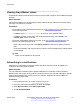
Introduction Viewing Avaya Mentor videos Avaya Mentor videos provide technical content on how to install, configure, and troubleshoot Avaya products. About this task Videos are available on the Avaya Support website, listed under the video document type, and on the Avaya-run channel on YouTube. Procedure • To find videos on the Avaya Support website, go to http://support.avaya.com and perform one of the following actions: - In Search, type Avaya Mentor Videos to see a list of the available videos.
Related resources 5. In the GENERAL NOTIFICATIONS area, select the required documentation types, and then click UPDATE. 6. Click OK. 7. In the PRODUCT NOTIFICATIONS area, click Add More Products. 8. Scroll through the list, and then select the product name. 9. Select a release version. 10. Select the check box next to the required documentation types. October 2015 Administering Avaya VSP 7200 Series and 8000 Series Comments on this document? infodev@avaya.
Introduction 11. Click Submit. Support Go to the Avaya Support website at http://support.avaya.com for the most up-to-date documentation, product notices, and knowledge articles. You can also search for release notes, downloads, and resolutions to issues. Use the online service request system to create a service request. Chat with live agents to get answers to questions, or request an agent to connect you to a support team if an issue requires additional expertise.
Support 3. In the Search dialog box, select the option In the index named .pdx. 4. Enter a search word or phrase. 5. Select any of the following to narrow your search: • Whole Words Only • Case-Sensitive • Include Bookmarks • Include Comments 6. Click Search. The search results show the number of documents and instances found. You can sort the search results by Relevance Ranking, Date Modified, Filename, or Location. The default is Relevance Ranking.
Chapter 2: New in this release The following sections detail what is new in Administering Avaya Virtual Services Platform 7200 Series and 8000 Series, NN47227-600. VOSS 4.2.1 Features See the following sections for information about feature changes. Autonegotiation updates Configuring Ethernet ports with Autonegotiation on page 77 and Configuring basic port parameters on page 87 are updated to include VSP 7200 Series.
VOSS 4.2 For more information, see Supported RFCs on page 221. Secure Shell (SSHv2) VOSS 4.2.1 introduces the command enable ssh sftp, which allows you to disable SFTP while SSH remains active. For more information, see Disabling SFTP without disabling SSH on page 159. VOSS 4.2 Features See the following sections for information about feature changes. Channelization Channelization allows you to configure 40Gbps QSFP+ ports to operate as four 10 Gigabit Ethernet ports.
New in this release • Variable definitions on page 42. Request for comment (RFC) updates VOSS 4.2 release updates the RFC information to add support for the following RFCs: • RFC 2407 • RFC 2408 • RFC 4301 • RFC 4302 • RFC 4303 • RFC 4305 • RFC 4308 • RFC 4552 • RFC 4835 For more information, see Supported RFCs on page 221. Secure Copy (SCP) changes The current release does not support Secure Copy (SCP). This release supports Secure File Transfer Protocol (SFTP) to transfer files securely.
VOSS 4.2 Serial ports interrupted due to link disconnection, power failure, or other reasons force out the user and end the user session. Ending the user session ensures a maintenance port is not available with an active session that can allow unauthorized use by someone other than the authenticated user, and prevents the physical hijacking of an active session by unplugging the connected cable and plugging in another. For more information, see Configuring serial management port dropping on page 80.
Chapter 3: Basic administration The following sections describe common procedures to configure and monitor the switch. Basic administration procedures using ACLI The following section describes common procedures that you use while you configure and monitor the switch operations. Note: Unless otherwise stated, to perform the procedures in this section, you must log on to the Privileged EXEC mode in Avaya Command Line Interface (ACLI).
Basic administration procedures using ACLI Example Switch:1> enable Save the configuration to the default location: Switch:1# save config Identify the file as a backup file and designate a location to save the file: Switch:1# save config Variable definitions Use the data in the following table to use the save config command. Variable Value backup WORD<1–99> Saves the specified file name and identifies the file as a backup file. WORD<1–99> uses one of the following format: • a.b.c.
Basic administration About this task Restart the switch to implement configuration changes or recover from a system failure. When you restart the system, you can specify the boot config file name. If you do not specify a boot source and file, the boot command uses the configuration files on the primary boot device defined by the boot config choice command. After the switch restarts normally, it sends a cold trap within 45 seconds after the restart. Procedure 1. Enter Privileged EXEC mode: enable 2.
Basic administration procedures using ACLI Resetting the platform About this task Reset the platform to reload system parameters from the most recently saved configuration file. Procedure 1. Enter Privileged EXEC mode: enable 2. Reset the switch: reset [-y] Example Switch:1> enable Reset the switch: Switch:1# reset Are you sure you want to reset the switch? (y/n) y Variable definitions Use the data in the following table to use the reset command.
Basic administration sys shutdown 3. Before you unplug the power cord, wait until you see the following message: System Halted, OK to turn off power Example Shut down a running system. Switch:1#sys shutdown Are you sure you want shutdown the system? Y/N (y/n) ? y CP1 [05/08/14 15:47:50.164] 0x00010813 00000000 GlobalRouter HW INFO System shutdown initiated from CLI CP1 [05/08/14 15:47:52.000] LifeCycle: INFO: Stopping all processes CP1 [05/08/14 15:47:53.
Basic administration procedures using ACLI Example Ping an IP device from a GRT VLAN IP interface: Switch:1# ping 192.0.2.16 192.0.2.16 is alive Variable definitions Use the data in the following table to use the ping command. Variable Value count <1–9999> Specifies the number of times to ping (1–9999). -d Configures the ping debug mode.
Basic administration Variable Value source WORD <1–256> Specifies an IP address to be used as the source IP address in the packet header. -t <1–120> Specifies the no-answer timeout value in seconds (1–120). vrf WORD<0–16> Specifies the virtual routing and forwarding (VRF) name from 1–16 characters. WORD<0–256> Specifies the host name or IPv4 (a.b.c.d) address (string length 0–256). Specifies the address to ping.
Basic administration procedures using ACLI Table 3: Variable definitions Variable Value -a Adds data to the output file instead of overwriting it. You cannot use the -a option with the -c option. -c Compares the checksum of the specified file by WORD<1–99> with the MD5 checksum present in the checksum file name. You can specify the checksum file name using the -f option. If the checksum filename is not specified, the file / intflash/checksum.md5 is used for comparison.
Basic administration Resetting system functions About this task Reset system functions to reset all statistics counters, the console port (10101). Procedure 1. Enter Privileged EXEC mode: enable 2. Reset system functions: sys action reset {console|counters} Example Switch:1> enable Reset the statistics counters: Switch:1> sys action reset counters Are you sure you want to reset system counters (y/n)? y Variable definitions Use the data in the following table to use the sys action command.
Basic administration procedures using EDM 2. Source a configuration: source WORD<1–99> [debug] [stop] [syntax] Example Switch:1> enable Debug the script output: Switch:1# source testing.cfg debug Variable definitions Use the data in the following table to use the source command. Table 5: Variable definitions Variable Value debug Debugs the script output. stop Stops the merge after an error occurs. syntax Verifies the script syntax.
Basic administration 3. Click Chassis. 4. Click the System tab. 5. Locate ActionGroup4 near the bottom of the screen. 6. Select softReset from ActionGroup4. 7. Click Apply. Showing the MTU for the system About this task Perform this procedure to show the MTU configured for the system. Procedure 1. On the Device Physical View, select the Device. 2. In the navigation tree, open the following folders: Configuration > Edit. 3. Click Chassis. 4. Click on the Chassis tab. 5.
Basic administration procedures using EDM Name Description UsbBytesUsed Specifies the number of bytes used in USB device. UsbBytesFree Specifies the number of bytes available for use in USB device. UsbNumFiles Specifies the number of files in USB device. Displaying available storage space About this task Display information about the available space for storage devices on this system. Procedure 1. In the navigation tree, open the following folders: Configuration > Edit. 2. Click Chassis. 3.
Basic administration Name Description Slot Specifies the slot number of the device. Name Specifies the directory name of the file. Date Specifies the creation or modification date of the file. Size Specifies the size of the file. Displaying internal flash files Display information about the files on the internal flash. Procedure 1. In the navigation tree, expand the following folders: Configuration > Edit. 2. Click Chassis. 3. Click the Flash Files tab.
Basic administration procedures using EDM Name Description Slot Specifies the slot number of the device. Name Specifies the directory name of the file. Date Specifies the creation or modification date of the file. Size Specifies the size of the file. Copying a file About this task Copy files on the internal flash. Procedure 1. In the navigation tree, open the following folders:Configuration > Edit. 2. Click File System. 3. Click the Copy File tab. 4. Edit the fields as required. 5. Click Apply.
Basic administration Saving the configuration About this task After you change the configuration, you must save the changes on the device. Save the configuration to a file to retain the configuration settings. Note: When you logout of the EDM interface, a dialogue box automatically prompts if you want to save the configuration. If you want to save the configuration, click OK. If you want to close without saving the configuration, click Cancel.
Chapter 4: System startup fundamentals This section provides conceptual material on the boot sequence and boot processes of the switch. Review this content before you make changes to the configurable boot process options. spbm-config-mode boot flag Shortest Path Bridging (SPB) and Protocol Independent Multicast (PIM) cannot interoperate with each other on the switch at the same time. To ensure that SPB and PIM stay mutually exclusive, Avaya implemented a new boot flag called spbm-config-mode.
System startup fundamentals Figure 1: Boot sequence Stage 1: Loading Linux The port contains a boot flash partition that stores the boot images, which include the boot loader, and the Linux kernel and applications. The boot flash partition contains two versions of the boot October 2015 Administering Avaya VSP 7200 Series and 8000 Series Comments on this document? infodev@avaya.
Boot sequence image: a committed version (the primary release) and a backup version. A committed version is one that is marked as good (if you can start the system using that version). The system automatically uses the backup version if the system fails the first time you start with a new version. Stage 2: Loading the primary release The switch can install a maximum of six releases but can only load one of two—a primary (committed) release or a backup release.
System startup fundamentals Table 6: Configuration file statements Sample statement # software version Action : 4.0.0.0 Adds clarity to the configuration by identifying the software version. Configures the flag to the false condition, prior to loading the general configuration. #!no boot config flags sshd Boot sequence modification You can change the boot sequence in the following ways: • Change the primary designations for file sources. • Change the file names from the default values.
System connections The following table lists parameters you configure in ACLI using the boot config flags command. For information on system flags and their configuration, see Configuring system flags on page 47.
System startup fundamentals Client and server support The client-server model partitions tasks between servers that provide a service and clients that request a service. For active ACLI clients, users initiate a client connection from the VSP switch to another device. For non-active clients, the client exists on the switch and the switch console initiates the request, with no intervention from users after the initial setup. For instance, Network Time Protocol (NTP) is a non active client.
Client and server support The switch supports the following servers using IPv4: • File Transfer Protocol (FTP) • Hypertext Transfer Protocol (HTTP) • Hypertext Transfer Protocol Secure (HTTPS) • remote shell (rsh) • rlogin • Secure Copy (SCP) Note: The current release does not support Secure Copy (SCP).
Chapter 5: Boot parameter configuration using ACLI Use the procedures in this section to configure and manage the boot process. • To perform the procedures in this section, you must log on to Global Configuration mode in ACLI. For more information about how to use ACLI and how to log on to the software, see Using ACLI and EDM on Avaya Virtual Services Platform 7200 Series and 8000 Series, NN47227-103.
Configuring the remote host logon Switch:1# boot config flags factorydefaults Configuring the remote host logon Before you begin • The FTP server must support the FTP passive (PASV) command. If the FTP server does not support the passive command, the file transfer is aborted, and then the system logs an error message that indicates that the FTP server does not support the passive command. About this task Configure the remote host logon to modify parameters for FTP and TFTP access.
Boot parameter configuration using ACLI About this task File Transfer Protocol (FTP), Trivial File Transfer Protocol (TFTP), remote login (rlogin), Secure Shell version 2 (SSHv2), and Telnet server support IPv4 addresses. Procedure 1. Enter Global Configuration mode: enable configure terminal 2. Enable the access service: boot config flags {ftpd|rlogind|sshd|telnetd|tftpd} 3. Save the configuration.
Enabling remote access services Variable Value • debug-config [file]— Logs the line-by-line configuration file processing and result of the execution to the debug file while the device loads the configuration file. The system logs the debug config output to /intflash/debugconfig_primary.txt for the primary configuration file. The system logs the debug config output to /intflash/ debugconfig_backup.txt for the backup configuration, if the backup configuration file loads.
Boot parameter configuration using ACLI Variable Value secure passwords. If you operate the switch in High Secure mode, the switch prompts a password change if you enter invalid-length passwords. logging The logging command is used to activate or disable system logging. The default value is enabled. The system names log files according to the following: • File names appear in 8.3 (log.xxxxxxxx.sss) format.
Enabling remote access services Variable Value telnetd Activates or disables the Telnet server service. The default is disabled. tftpd Activates or disables Trivial File Transfer Protocol server service. The default value is disabled. trace-logging Activates or disables the creation of trace logs. The default value is disabled. Important: Do not change this parameter unless directed by Avaya. verify-config Activates syntax checking of the configuration file. The default is enabled.
Boot parameter configuration using ACLI Changing the primary or secondary boot configuration files About this task Change the primary or secondary boot configuration file to specify which configuration file the system uses to start. Configure the primary boot choices. You have a primary configuration file that specifies the full directory path and a secondary configuration file that also contains the full directory path. Procedure 1. Enter Global Configuration mode: enable configure terminal 2.
Configuring boot flags using ACLI Table 9: Variable definitions Variable Value {backup-config-file|config-file} Specifies that the boot source uses either the configuration file or a backup configuration file. WORD<0–255> Identifies the configuration file. WORD<0–255> is the device and file name, up to 255 characters including the path, in one of the following format: • a.b.c.d: • /usb/” • /intflash/ To set this option to the default value, use the default operator with the command.
Boot parameter configuration using ACLI no boot config flags 4. Configure the boot flag to the default value: default boot config flags 5.
Configuring boot flags using ACLI Variable Value The options are: • debug-config [console]—Displays the line-by-line configuration file processing and result of the execution on the console while the device loads the configuration file. • debug-config [file]— Logs the line-by-line configuration file processing and result of the execution to the debug file while the device loads the configuration file. The system logs the debug config output to /intflash/debugconfig_primary.
Boot parameter configuration using ACLI Variable Value • The password must contain a minimum of 2 uppercase characters, 2 lowercase characters, 2 numbers, and 2 special characters. • Aging time • Failed login attempt limitation The default value is disabled. If you enable High Secure mode, you must restart the switch to enforce secure passwords. If you operate the switch in High Secure mode, the switch prompts a password change if you enter invalid-length passwords.
Configuring boot flags using ACLI Variable Value Use the no operator so that you can configure PIM and IGMP. The boot flag is enabled by default. To set this flag to the default value, use the default operator with the command. sshd Activates or disables the SSHv2 server service. The default value is enabled. telnetd Activates or disables the Telnet server service. The default is disabled. tftpd Activates or disables Trivial File Transfer Protocol server service. The default value is disabled.
Boot parameter configuration using ACLI Configuring serial port devices About this task Configure the serial port devices to define connection settings for the console port (10101). Procedure 1. Enter Global Configuration mode: enable configure terminal 2. Optionally, specify 8 data bits: boot config sio console 8databits 3. Optionally, change the baud rate for the port: boot config sio console baud <9600–115200> 4. Save the changed configuration. 5. Restart the switch.
Displaying the boot configuration Variable Value The default value is 9600. To configure this option to the default value, use the default operator with the command. Displaying the boot configuration About this task Display the configuration to view current or changed settings for the boot parameters. Procedure 1. Enter Privileged EXEC mode: enable 2. View the configuration: show boot config Example Show the current boot configuration.
Boot parameter configuration using ACLI Table 12: Variable definitions Variable Value choice Shows the current boot configuration choices. flags Shows the current flag settings. general Shows system information. host Shows the current host configuration. running-config [verbose] Shows the current boot configuration. If you use verbose, the system displays all possible information. If you omit verbose, the system displays only the values that you changed from their default value.
Chapter 6: Run-time process management using ACLI Configure and manage the run-time process using the Avaya Command Line Interface (ACLI). To perform the procedures in this section, you must log on to Global Configuration mode in ACLI. For more information about how to use ACLI, see Using ACLI and EDM on Avaya Virtual Services Platform 7200 Series and 8000 Series, NN47227-103. Configuring the date About this task Configure the calendar time in the form of month, day, year, hour, minute, and second.
Run-time process management using ACLI Table 13: Variable definitions Variable Value MMddyyyyhhmmss Specifies the date and time in the format month, day, year, hour, minute, and second. Configuring the time zone About this task Configure the time zone to use an internal system clock to maintain accurate time. The time zone data in Linux includes daylight changes for all time zones up to the year 2038. You do not need to configure daylight savings.
Configuring the run-time environment Table 14: Variable definitions Variable Value WORD<1–10> Specifies a directory name or a time zone name in /usr/share/zoneinfo, for example, Africa, Australia, Antarctica, or US. To see a list of options, enter clock time-zone at the command prompt without variables. WORD<1–20> WORD<1–20> The first instance of WORD<1–20> is the area within the timezone. The value represents a time zone data file in /usr/share/zoneinfo/ WORD<1–10>/, for example, Shanghai in Asia.
Run-time process management using ACLI terminal length <8–64> 8.
Configuring the run-time environment Variable Value • Use the no operator before this parameter, no loginmessage, to disable the default logon banner and display the new banner. Use the data in the following table to use the passwordprompt command. Table 16: Variable definitions Variable Value WORD<1-1510> Changes the ACLI password prompt. • WORD<1-1510> is an ASCII string from 1–1510 characters.
Run-time process management using ACLI Table 20: Variable definitions Variable Value <8–64> Configures the number of lines in the output display for the current session. To configure this option to the default value, use thedefault operator with the command. The default is value 23. disable|enable Configures scrolling for the output display. The default is enabled. Use the no operator to remove this configuration.
Configuring the message-of-the-day Table 21: Variable definitions Variable Value custom|static Activates or disables use of the default banner. displaymotd Enables displaymotd. motd Sets the message of the day banner. WORD<1–80> Adds lines of text to the ACLI logon banner. Configuring the message-of-the-day About this task Configure a system login message-of-the-day in the form of a text banner that appears after each successful logon. Procedure 1.
Run-time process management using ACLI Table 22: Variable definitions Variable Value WORD<1–1516> Creates a message of the day to display with the logon banner. To provide a string with spaces, include the text in quotation marks ("). To set this option to the default value, use the default operator with the command. Configuring ACLI logging About this task Use ACLI logging to track all ACLI commands executed and for fault management purposes.
Configuring system parameters Variable definitions Use the data in the following table to use the clilog commands. Table 23: Variable definitions Variable Value enable Activates ACLI logging. To disable, use the no clilog enable command. Configuring system parameters About this task Configure individual system-level switch parameters to configure global options for the switch. Procedure 1. Enter Global Configuration mode: enable configure terminal 2. Change the system name: sys name WORD<0–255> 3.
Run-time process management using ACLI Variable definitions Use the data in the following table to use the sys command. Table 24: Variable definitions Variable Value mtu <1522|9600> Activates Jumbo frame support for the data path. The value can be either 1522, 1950 (default), or 9600 bytes. 1950 or 9600 bytes activate Jumbo frame support. name WORD<0–255> Configures the system, or root level, prompt name for the switch.
Extending system message control sys msg-control control-interval <1-30> 5.
Run-time process management using ACLI To enable the message control feature, you must specify an action, control interval, and maximum message number. After you enable the feature, the log messages, which get repeated and cross the maximum message number in the control interval, trigger the force message feature. You can either suppress the message or send a trap notification, or both. Procedure 1. Enter Global Configuration mode: enable configure terminal 2.
Chapter 7: Chassis operations The following sections provide information for chassis operations such as hardware and software compatibility. Chassis operations fundamentals This section provides conceptual information for chassis operations such as hardware and software compatibility and power management. Read this section before you configure the chassis operations.
Chassis operations If you want out-of-band management, Avaya recommends that you define a specific static route in the Management Router VRF to the IP subnet where your management application resides. When you specify a static route in the Management Router VRF, it enables the client management applications originating from the switch to perform out-of-band management without affecting inband management. This enables in-band management applications to operate in the Global Router VRF.
Chassis operations fundamentals • a software process that enters an infinite loop The software lock-up detect feature monitors processes to ensure that the software functions within expected time limit. The CPU logs detail about suspended tasks in the log file. For additional information about log files, see Managing Faults on Avaya Virtual Services Platform 7200 Series and 8000 Series, NN47227-702.
Chassis operations Channelization Channelization allows you to configure 40 Gbps QSFP+ ports to operate as four 10 Gigabit Ethernet ports. You can use QSFP+ to four SFP+ breakout cables or QSFP+ transceivers with fiber breakout cables to connect the 10 Gigabit Ethernet ports to other servers, storage, and switches. By default, the ports are not channelized, which means that the 40 Gbps QSFP+ ports operate as 40 Gigabit Ethernet ports. You can enable or disable channelization on a port.
Chassis operations configuration using ACLI Procedure 1. Enter Global Configuration mode: enable configure terminal 2. Enable jumbo frames: sys mtu <1950|1522|9600> Example Switch:1> enable Switch:1# configure terminal Enable jumbo frames to 9600 bytes: Switch:1#(config)# sys mtu 9600 Variable definitions Use the data in the following table to use the sys mtu command. Table 27: Variable definitions Variable Value 1950|9600 Configures the frame size support for the data path.
Chassis operations interface gigabitethernet {slot/port[/sub-port][-slot/port[/subport]][,...]} 4. Lock a port: lock port {slot/port[/sub-port][-slot/port[/sub-port]][,...
Chassis operations configuration using ACLI enable configure terminal 2. Disable SONMP: no autotopology 3. Enable SONMP: autotopology Example Switch:1> enable Switch:1 configure terminal Disable SONMP: Switch:1(config)# no autotopology Viewing the topology message status About this task View topology message status to view the interconnections between Layer 2 devices in a network. Procedure 1. Log on to the switch to enter User EXEC mode. 2.
Chassis operations Note: When a peer switch is running an older software version that does not include support for SONMP hello messages with channelization information, it can only show the slot/port. It cannot show the sub-port. Job aid The following table describes the column headings in the command output for show autotopology nmm-table. Table 29: Variable definitions Variable Value Local Port Specifies the slot and port that received the topology message.
Chassis operations configuration using ACLI About this task You can assign a VRF instance to a port after you configure the VRF. The system assigns ports to the Global Router, VRF 0, by default. Procedure 1. Enter Interface Configuration mode: enable configure terminal interface GigabitEthernet {slot/port[/sub-port][-slot/port[/subport]][,...
Chassis operations Note: For more information about the management port, see Administering Avaya Virtual Services Platform 7200 Series and 8000 Series. Procedure 1. Enter mgmtEthernet Interface Configuration mode: enable configure terminal interface mgmtEthernet mgmt 2. Configure the IP address and mask for the management port: ip address 3. Configure an IPv6 address and prefix length for the management port: ipv6 interface address WORD<0-255> 4.
Chassis operations configuration using ACLI Configuring Ethernet ports with Autonegotiation Configure Ethernet ports so they operate optimally for your network conditions. These ports use the Small Form Factor Pluggable plus (SFP+) transceivers. The default is enabled for VSP 8000 Series but disabled for VSP 7200 Series.
Chassis operations Example Switch:>enable Switch:1#configure terminal Switch:1(config)#interface gigabitethernet 4/2 Switch:1(config-if)#auto-negotiate enable Variable definitions Use the data in following table to use the auto-negotiate command. Variable Value {slot/port[/sub-port][-slot/port[/sub-port]][,...]} Specifies the port or ports that you want to configure. enable Enables Autonegotiation for the port or other ports of the module.
Chassis operations configuration using ACLI Variable Value transceiver, the system applies autonegotiation. If you install a 10 GbE transceiver, the system does not remove the autonegotiation settings from the configuration, but the system simply ignores the configuration because autonegotiation settings are irrelevant to a 10 GbE transceiver. The system preserves the saved configuration for autonegotiation when resaved no matter which speed of transceiver you install.
Chassis operations 4. To disable channelization on a port, enter: no channelize [port {slot/port/sub-port[-slot/port/sub-port][,...
Chassis operations configuration using ACLI Serial ports interrupted due to link disconnection, power failure, or other reasons force out the user and end the user session. Ending the user session ensures a maintenance port is not available with an active session that can allow unauthorized use by someone other than the authenticated user, and prevents the physical hijacking of an active session by unplugging the connected cable and plugging in another.
Chassis operations Example Enable power to Slot 1: Switch:1 (config)# sys power slot 1 Disable power to Slot 1: Switch:1 (config)# no sys power slot 1 Enable power to Slots 1 and 2: Switch:1 (config)# sys power slot 1, 2 Disable power to Slots 1 and 2: Switch:1 (config)# no sys power slot 1, 2 Variable definitions Use the data in the following table to use the sys power slot command. Variable Value {slot[-slot][,...
Chassis operations configuration using EDM 7. Type the location information in the sysLocation field. 8. Click Apply. System field descriptions Use the data in the following table to use the System tab. Name Description sysDescr Shows the system assigned name and the software version. sysUpTime Shows the elapsed time since the system last started. sysContact Configures the contact information (in this case, an email address) for the Avaya support group. sysName Configures the name of this device.
Chassis operations Name Description ActionGroup3 Can be the following action: • flushIpRouteTbl—flushes IP routes from the routing table ActionGroup4 Can be the following action: • softReset—resets the device without running power-on tests • resetConsole—resets the switch console Result Displays a message after you click Apply. Editing chassis information About this task Edit the chassis information to make changes to chassis-wide settings. Procedure 1.
Chassis operations configuration using EDM Name Description MacAddrCapacity Specifies the number of routable MAC addresses based on the BaseMacAddr. AutoRecoverDelay Specifies the time interval, in seconds, after which autorecovery runs on ports to clear actions taken by CP Limit or link flap. The default is 30. MTUSize Configures the maximum transmission unit size. The default is 1950. MgidUsageVlanCurrent Number of MGIDs for VLANs currently in use.
Chassis operations Important: After you change certain configuration parameters, you must save the changes to the configuration file. System Flags field descriptions Use the data in the following table to use the System Flags tab. Name Description EnableAccessPolicy Activates access policies. The default is disabled. ForceTrapSender Configures circuitless IP as a trap originator. The default is disabled.
Chassis operations configuration using EDM 7. To disable channelization on a port, select the first sub-port for the corresponding port: slot/ port/1. 8. In the navigation tree, expand the following folders: Configuration > Edit > Port. 9. Click General. 10. Click the Channelization tab. 11. To disable channelization on the port, select the disable button. This action will disable the four sub-ports. 12. Click the Apply button.
Chassis operations and duplex settings, you can manually configure the settings for the link in question. Check the Avaya Web site for the latest compatibility information. 6. Click Apply. Interface field descriptions Use the data in the following table to use the Interface tab. Name Description Index Displays the index of the port, written in the slot/port[/ sub-port] format. Name Configures the name of the port. Descr Displays the description of the port.
Chassis operations configuration using EDM Name Description The default is enabled for VSP 8000 Series but disabled for VSP 7200 Series. Note: The 10 GigabitEthernet fiber-based ports can operate at either 1 Gigabit per second (Gbps) or 10 Gbps, dependent upon the capabilities of the optical transceiver that you install.
Chassis operations Name Description Note that the 8424XT ESM does not support the following speeds: 10-full, 10-half, and 1000-half. AdminDuplex Configures the administrative duplex setting for the port. The switch does not support half duplex. OperDuplex Indicates the operational duplex setting for the port. The switch does not support half duplex. AdminSpeed Configures the administrative speed for the port. OperSpeed Indicates the operational speed for the port.
Chassis operations configuration using EDM Name Description EgressRateLimit Configures the egress rate limit in Kb/s. VSP supports the range 1000 to 40000000. If configured to 0, it means this option is disabled.
Chassis operations Name Description EnableFactoryDefaults Specifies whether the switch uses the factory default settings at startup. The default value is disabled. This flag is automatically reset to the default setting after the CPU restarts. If you change this parameter, you must restart the switch. EnableDebugMode Enabling the debugmode will provide the opportunity to allow user to enable TRACE on any port by prompting the selection on the console during boot up.
Chassis operations configuration using EDM Configuring boot flags About this task Change the boot configuration to determine the services available after the system starts. File Transfer Protocol (FTP), Trivial File Transfer Protocol (TFTP) and Telnet server support IPv4 addresses. Procedure 1. In the navigation tree, open the following folders: Configuration > Edit > Chassis. 2. Click the Boot Config tab. 3. Select the services you want to enable. 4. Click Apply.
Chassis operations Name Description Important: Do not change this parameter unless directed by Avaya. EnableTelnetServer Activates or disables the Telnet server service. The default is disabled. EnableRloginServer Activates or disables the rlogin and rsh server. The default value is disabled. EnableFtpServer Activates or disables the FTP server on the switch. The default value is disabled. To enable FTP, ensure that the TFTPD flag is disabled.
Chassis operations configuration using EDM Configuring the date and time About this task Configure the date and time to correctly identify when events occur on the system. Procedure 1. On the Device Physical View, select the Device. 2. In the navigation tree, open the following folders: Configuration > Edit. 3. Click Chassis. 4. Click the User Set Time tab. 5. Type and select the correct details. 6. Click Apply.
Chassis operations Procedure 1. In the Device Physical View tab, select a port. 2. In the navigation tree, open the following folders: Configuration > Edit > Port. 3. Click General. 4. Click the VRF tab. 5. To the right of the BrouterVrfId box, click the ellipsis (...) button. 6. In the BrouterVrfId dialog box, select the required VRF. 7. Click OK. 8. Click Apply.
Chassis operations configuration using EDM Before you begin • You must make a direct connection through the console port to configure a new IP address. If you connect remotely, you can view or delete the existing IP address configuration. If you delete the IP address remotely, you lose the EDM connection to the device. • Do not configure a default route in the Management VRF.
Chassis operations 12. Collapse the VRF context view. IP Address field descriptions Use the data in the following table to use the IP Address tab. Name Description Interface Specifies the slot and port for the management port. Ip Address Specifies the IP address for the management port. Net Mask Specifies the subnet mask for the IP address. BcastAddrFormat Specifies the broadcast address format for the management port.
Chassis operations configuration using EDM 4. Click the General tab. 5. Modify the appropriate settings. 6. Click Apply. General field descriptions Use the data in the following table to use the General tab. Name Description Index Specifies the slot and port number of the management port. AdminStatus Configures the administrative status of the device as up (ready to pass packets) or down. The testing state indicates that no operational packets can be passed.
Chassis operations Name Description autonegotiation. If you install a 10 GbE transceiver, the system does not remove the autonegotiation settings from the configuration, but the system simply ignores the configuration because autonegotiation settings are irrelevant to a 10 GbE transceiver. The system preserves the saved configuration for autonegotiation when resaved no matter which speed of transceiver you install. AdminDuplex Specifies the administrative duplex mode for the management port.
Chassis operations configuration using EDM Name Description ReasmMaxSize(MTU) Configures the MTU for this IPv6 interface. This value must be the same for all the IP addresses defined on this interface. The default value is 1500. PhysAddress Specifies the physical address for the interface. For example, for an IPv6 interface attached to an 802.x link, this value is a MAC address. AdminStatus Configures the indication of whether IPv6 is activated (up) or disabled (down) on this interface.
Chassis operations IPv6 Addresses field descriptions Use the data in the following table to use the IPv6 Addresses tab. Name Description Interface Specifies an index value that uniquely identifies the interface. Addr Specifies the IPv6 address to which this entry addressing information pertains. If the IPv6 address exceeds 116 octets, the object identifiers (OIDS) of instances of columns in this row is more than 128 subidentifiers and you cannot use SNMPv1, SNMPv2c, or SNMPv3 to access them.
Chassis operations configuration using EDM Editing serial port parameters About this task Perform this procedure to specify serial port communication settings. The serial port on the device is the console port (10101). Procedure 1. In the Device Physical View tab, select the console port (10101) on the device. 2. In the navigation tree, open the following folders: Configuration > Edit. 3. Click Serial Port. 4. Edit the port parameters as required.
Chassis operations Name Description Enable Activates the port lock feature. Clear this check box to unlock ports. The default is disabled. LockedPorts Lists the locked ports. Click the ellipsis (...) button to select the ports you want to lock or unlock. Locking a port Before you begin • You must enable port lock before you lock or unlock a port.
Chassis operations configuration using EDM Procedure 1. On the Device Physical View, select the Device. 2. In the navigation tree, open the following folders: Configuration > Edit. 3. Click Chassis. 4. Click the Power Info tab. Power Info field descriptions Use the data in the following table to use the Power Info tab. Name Description TotalPower Shows the total power for the chassis. RedundantPower Shows the redundant power for the chassis.
Chassis operations Viewing fan information About this task View fan information to monitor the alarm status of the cooling ports in the chassis. Procedure 1. On the Device Physical View, select the Device. 2. In the navigation tree, open the following folders: Configuration > Edit. 3. Click Chassis. 4. Click the Fan Info tab. Fan Info field descriptions Use the data in the following table to use the Fan Info tab. Name Description Id Specifies the fan ID.
Chassis operations configuration using EDM Name Description NmmLstChg Specifies the value of sysUpTime, the last time an entry in the network management MIB (NMM) topology table was added, deleted, or modified, if the table did not change since the last cold or warm start of the agent. NmmMaxNum Specifies the maximum number of entries in the NMM topology table. NmmCurNum Specifies the current number of entries in the NMM topology table.
Chassis operations Name Description • heartbeat—Topology information is unchanged. • new—The sending agent is in a new state. Configuring a forced message control pattern About this task Configure a forced message control pattern to enforce configured message control actions. Procedure 1. In the navigation pane, expand the following folders: Configuration > Edit > Chassis. 2. Click the Force Msg Patterns tab. 3. Click Insert. 4. In the PatternId field, enter a pattern ID number. 5.
Chapter 8: Hardware status using EDM This section provides methods to check the status of basic hardware in the chassis using Enterprise Device Manager (EDM). Configuring polling intervals About this task Enable and configure polling intervals to determine how frequently EDM polls for port and LED status changes or detects the hot swap of installed ports. Procedure 1. In the navigation tree, open the following folders: Configuration > Device. 2. Click Preference Setting. 3.
Hardware status using EDM Viewing module information View the administrative status for modules in the front of the chassis. About this task This procedure applies only to VSP 8400. VSP 8400 provides slots for four Ethernet Switch Modules (ESM). Procedure 1. In the Device Physical View tab, select an ESM. 2. In the navigation tree, expand the following folders: Configuration > Edit. 3. Click Card. 4. Click the Card tab. Card field descriptions Use the data in the following table to use the Card tab.
Viewing temperature on the chassis Detail field descriptions Use the data in the following table to use the Detail tab. Name Description Type Describes the type of power used—AC or DC. Description Provides a description of the power supply. SerialNumber Specifies the power supply serial number. HardwareRevision Specifies the hardware revision number. PartNumber Specifies the power supply part number.
Hardware status using EDM 4. Click the Temperature tab. Temperature field descriptions Use the data in the following table to use the Temperature tab. Name Description CpuTemperature Current CPU temperature in Celsius. MacTemperature Current MAC component temperature in Celsius. Phy1Temperature Current PHY 1 component temperature in Celsius. This field does not apply to VSP 7254XSQ. Phy2Temperature Current PHY 2 component temperature in Celsius. This field does not apply to VSP 7254XSQ.
Chapter 9: Domain Name Service The following sections provide information on the Domain Name Service (DNS) implementation for the switch. DNS fundamentals This section provides conceptual material on the Domain Name Service (DNS) implementation for the switch. Review this content before you make changes to the configurable DNS options. DNS client Every equipment interface connected to a Transmission Control Protocol over IP (TCP/IP) network is identified with a unique IPv4 or IPv6 address.
Domain Name Service IPv6 Support The Domain Name Service (DNS) used by the switch supports both IPv4 and IPv6 addresses with no difference in functionality or configuration. DNS configuration using ACLI This section describes how to configure the Domain Name Service (DNS) client using Avaya command line interface (ACLI). DNS supports IPv4 and IPv6 addresses.
DNS configuration using ACLI Variable definitions Use the data in the following table to use the ip domain-name command. Table 30: Variable definitions Variable Value WORD<0–255> Configures the default domain name. WORD<0–255> is a string 0–255 characters. Use the data in the following table to use the ip name-server command. Table 31: Variable definitions Variable Value primary|secondary|tertiary WORD<0–46> Configures the primary, secondary, or tertiary DNS server address.
Domain Name Service Switch:1(config)# show hosts 10.10.10.1 Variable definitions Use the data in the following table to use the show hosts command. Table 32: Variable definitions Variable Value WORD<0–256> Specifies one of the following: • the name of the host DNS server as a string of 0– 256 characters. • the IP address of the host DNS server in a.b.c.d format. • The IPv6 address of the host DNS server in hexadecimal format (string length 0–46).
DNS configuration using EDM 6. In the DnsServerListAddressType box, select the IP version. 7. In the DnsServerListAddress box, enter the DNS server IP address. 8. Click Insert. DNS Servers field descriptions Use the data in the following table to use the DNS Servers tab. Name Description DnsServerListType Configures the DNS server as primary, secondary, or tertiary. DnsServerListAddressType Configures the DNS server address type as IPv4 or IPv6.
Domain Name Service Name Description HostAddressType Identifies the address type of the host. HostAddress Identifies the host IP address. This variable is a read-only field. HostSource Identifies the DNS server IP or host file. This variable is a read-only field. October 2015 Administering Avaya VSP 7200 Series and 8000 Series Comments on this document? infodev@avaya.
Chapter 10: Licensing The following sections provide information on the Licensing features, activation, and installation on the switch. Licensing fundamentals This section provides conceptual information about feature licensing for the switch. Review this section before you make changes to the license configuration. Feature licensing This product uses the Product Licensing and Delivery System (PLDS) as the license order, delivery and management tool.
Licensing Base License The Base License is included with the switch hardware and activates the features not included in the Premier License. The Base License includes the following Layer 2 features: • VLANs • RSTP • MSTP • MLT • IGMP • 802.1AX Link Aggregation (LACP) • 802.
Licensing fundamentals • IPv6 • SMLT Premier License The Premier License activates the Layer 3 Virtualization features, that is the Layer 3 Virtual Service Networks in addition to the Base License. Important: Avaya recommends that you purchase the Premier License if you anticipate growth in your network. You can install a Premier License on each chassis after you install the Base software license, and it is optional.
Licensing Feature license files After you obtain the license file to enable Premier License features, you must install the license file on the system to unlock the associated licensed features. You must load a license file on the internal flash of the device. License installation using ACLI Install and manage a license file for the switch by using the Avaya command line interface (ACLI).
License installation using ACLI Important: The license filename stored on a device must meet the following requirements: • Maximum of 63 alphanumeric characters • No spaces or special characters allowed • Underscore (_) is allowed • The file extension ".xml" is required Example Use FTP to transfer a license file from a PC to the internal flash on the device: C:\Users\jsmith>ftp 192.0.2.16 Connected to 192.0.2.16 (192.0.2.16). 220 FTP server ready Name (192.0.2.
Licensing Variable Value Specifies the name of the license file when copied to the flash. The destination file name must meet the following requirements: • Maximum of 63 alphanumeric characters • No spaces or special characters allowed • Underscore (_) is allowed • The file extension ".xml" is required Specifies the name of the license file on the TFTP server. For example, license.lic or license.xml.
License installation using EDM - Layer 3 VSNs MACsec License installation using EDM Install and manage a license file for the switch by using Enterprise Device Manager (EDM). Installing a license file Before you begin • You must store the license file on a file server. • Ensure that you have the correct license file with the base MAC address of the switch on which you need to install the license. Otherwise, the system does not unblock the licensed features.
Licensing Important: If the loading fails, the switch cannot unlock the licensed features and reverts to base functionality. 13. On the System tab, in ActionGroup1, select saveRuntimeConfig. 14. Click Apply. Important: The license filename stored on a device must meet the following requirements: • Maximum of 63 alphanumeric characters • No spaces or special characters allowed • Underscore (_) is allowed • The file extension ".
Chapter 11: Network Time Protocol The following sections provide information on the Network Time Protocol (NTP). NTP fundamentals This section provides conceptual material on the Network Time Protocol (NTP). Review this content before you make changes to the NTP configuration Overview The Network Time Protocol (NTP) synchronizes the internal clocks of various network devices across large, diverse networks to universal standard time.
Network Time Protocol NTP system implementation model NTP is based on a hierarchical model that consists of a local NTP client that runs on the switch and on remote time servers. The NTP client requests and receives time information from one or more remote time servers. The local NTP client reviews the time information from all available time servers and synchronizes its internal clock to the time server whose time is most accurate.
NTP fundamentals Time distribution within a subnet NTP distributes time through a hierarchy of primary and secondary servers, with each server adopting a stratum, see Figure 2: NTP time servers forming a synchronization subnet on page 128. A stratum defines how many NTP hops away a particular secondary time server is from an authoritative time source (primary time server) in the synchronization subnet.
Network Time Protocol After the NTP client queries the remote time servers, the servers respond with various timestamps, along with information about their clocks, such as stratum, precision, and time reference, see Figure 3: NTP time servers operating in unicast client mode on page 130. The NTP client reviews the list of responses from all available servers and chooses one as the best available time source from which to synchronize its internal clock.
NTP configuration using ACLI NTP configuration using ACLI This section describes how to configure the Network Time Protocol (NTP) using Avaya Command Line Interface (ACLI). Before you configure NTP, you must perform the following tasks: • Configure an IP interface on the switch and ensure that the NTP server is reachable through this interface. For instructions, see Configuring IP Routing on Avaya Virtual Services Platform 7200 Series and 8000 Series, NN47227-505.
Network Time Protocol Figure 4: NTP configuration procedures Enabling NTP globally Enable NTP globally. Default values are in effect for most parameters. You can customize NTP by modifying parameters. Procedure 1. Enter Global Configuration mode: enable configure terminal 2. (Optional) Set the time interval between NTP updates or leave it at the default of 15 minutes: October 2015 Administering Avaya VSP 7200 Series and 8000 Series Comments on this document? infodev@avaya.
NTP configuration using ACLI ntp interval <10-1440> Important: If NTP is already activated, this configuration does not take effect until you disable NTP, and then re-enable it. 3. Enable NTP globally: ntp 4. Create an authentication key: ntp authentication-key <1-2147483647> WORD<0–8> Example Specify the interval between NTP updates to 10 minutes, and then enable NTP globally.
Network Time Protocol Procedure 1. Enter Global Configuration mode: enable configure terminal 2. Add an NTP server: ntp server 3. Configure additional options for the NTP server: ntp server [auth-enable] [authentication-key <0-2147483647>] [source-ip WORD <0-46>] 4. Activate the NTP server: ntp server enable Example Switch:> enable Switch:1 configure terminal Switch:1(config)# ntp server 192.0.2.
NTP configuration using EDM ntp server auth-enable 4. Assign an authentication key to the server: ntp server authentication-key <0-2147483647> Example Switch:1> enable Switch:1# configure terminal Create the authentication key: Switch:1#(config)# ntp authentication-key 5 test Enable MD5 authentication for the NTP server: Switch:1#(config)# ntp server 192.0.2.187 auth-enable Assign an authentication key to the server: Switch:1#(config)# ntp server 192.0.2.
Network Time Protocol Before you configure NTP, you must perform the following tasks: • Configure an IP interface on the switch and ensure that the NTP server is reachable through this interface. For instructions, see Configuring IP Routing on Avaya Virtual Services Platform 7200 Series and 8000 Series, NN47227-505. Important: NTP server MD5 authentication does not support passwords (keys) that start with a special character or that contain a space between characters.
NTP configuration using EDM Enabling NTP globally About this task Enable NTP globally. Default values are in effect for most parameters. You can customize NTP by modifying parameters. Procedure 1. In the navigation tree, open the following folders: Configuration > Edit. 2. Click NTP. 3. Click the Globals tab. 4. Select the Enable check box. 5. Click Apply. Globals field descriptions Use the data in the following table to use the Globals tab.
Network Time Protocol 6. Click Insert. The IP address of the NTP server that you configured appears on the Server tab. Server field descriptions Use the data in the following table to use the Server tab. Name Description ServerAddress Specifies the IP address of the remote NTP server. Enable Activates or disables the remote NTP server. The default is enabled. Authentication Activates or disables MD5 authentication on this NTP server. MD5 produces a message digest of the key.
NTP configuration using EDM Key field descriptions Use the data in the following table to use the Key tab. Name Description KeyId This field is the key ID that generates the MD5 digest. You must specify a value between 1–214743647. The default value is 1, which indicates that authentication is disabled. KeySecret This field is the MD5 key that generates the MD5 digest.
Chapter 12: Secure Shell The following sections describe how to use Secure Shell (SSH) to enable secure communications support over a network for authentication, encryption, and network integrity. Secure Shell fundamentals Secure Shell (SSH) is a client and server protocol that specifies the way to conduct secure communications over a network. The traffic these utilities generate is not encrypted when using other methods of remote access such as Telnet or FTP.
Secure Shell fundamentals By using a combination of host, server, and session keys, the SSHv2 protocol can provide strong authentication and secure communication over an insecure network, offering protection from the following security risks: • IP spoofing • IP source routing • Domain name server (DNS) spoofing • Man-in-the-middle/TCP hijacking attacks • Eavesdropping and password sniffing Even if network security is compromised, traffic cannot be played back or decrypted, and the connection cannot be hija
Secure Shell Important: Do not enable SSHv2 secure mode using Configuration and Orchestration Manager (COM). If you enable SSHv2 secure mode, then the system disables Simple Network Management Protocol (SNMP). This locks you out of a COM session. Enable SSH secure mode using ACLI or EDM. SSHv2 secure mode is different from enhanced secure mode and hsecure. SSHv2 secure mode disables unsecure management protocols on the device such as FTP, rlogin, SNMP, telnet and TFTP.
Secure Shell fundamentals passphrase encrypts and further protects the key files, you must provide a passphrase to decrypt the key files as part of the DSA authentication. The following is an example of DSA public key authentication between the VSP SSHv2 client and the SSHv2 server: Linux/PC ssh (DSA authorization) > VSP ssh (DSA authorization) > VSP ssh (DSA authorization) > VSP To attempt public key authentication, the SSHv2 client looks for the associated DSA key pair files in the /intflash/.
Secure Shell Figure 7: Separate SSH version 2 protocols The modular approach of SSHv2 improves on the security, performance, and portability of the SSHv1 protocol. Important: The SSHv1 and SSHv2 protocols are not compatible. The VSP switch does not support SSHv1. October 2015 Administering Avaya VSP 7200 Series and 8000 Series Comments on this document? infodev@avaya.
Secure Shell fundamentals User ID log of an SSH session established by SFTP The VSP modular switch logs the user ID of an SSH session initiated by SFTP. If SFTP establishes an SSH session, the message appears in the following format: CP1 [03/12/13 21:49:11.374] 0x000d858b 00000000 ip 10.10.10.98 port 59826 CP1 [03/12/13 21:49:11.377] 0x000d8603 00000000 compatibility mode for protocol 2.0 CP1 [03/12/13 21:49:16.577] 0x000d8602 00000000 for ROOT from 10.10.10.98 port 59826 ssh2 CP1 [03/12/13 21:49:16.
Secure Shell SSH server SSH client side • rwl3—/intflash/.ssh/id_dsa_rwl3 (private key), /intflash/.ssh/ id_dsa_rwl3.pub (public key) SSH server side VOSS switch with enhanced secure mode enabled Private and public keys by access role level: Public keys on the server side based on access level: • administrator—/intflash/.ssh/ id_dsa_admin (private key), / intflash/.ssh/id_dsa_admin.pub (public key) • administrator—/intflash/.ssh/ dsa_key_admin (public key) • operator —/intflash/.
Secure Shell fundamentals Block SNMP The boot flag setting for block-snmp (boot config flags block-snmp) and the runtime configuration of SSH secure (ssh secure) each modify the block-snmp boot flag. If you enable SSH secure mode, the system automatically sets the block-snmp boot flag to true; the change takes effect immediately. After enabling SSH in secure mode, you can manually change the block-snmp flag to false to allow both SSH and SNMP access.
Secure Shell SSH Client Secure Shell (SSH) that a DSA key has been generated. Secure Copy (SCP) OpenSSH • Supports SSHv2 clients. Unix Solaris 2.5 / 2.6 • Authentication: • Client distribution includes an SCP client that is supported on The VSP modular switch. - RSA is supported when the switch acts as a server. The VSP switch does not support RSA as a client. - DSA - Password • Provides a keygen tool. • It creates both RSA and DSA keys.
Secure Shell fundamentals Table 38: DSA authentication access level and file name Client key format or WSM Client key in non IETF and IETF format with enhanced secure mode disabled Note: The VSP switch supports IETF and non-IETF for DSA. Client key in enhanced secure mode Access level File name RWA /intflash/.ssh/dsa_key_rwa RW /intflash/.ssh/dsa_key_rw RO /intflash/.ssh/dsa_key_ro L3 /intflash/.ssh/dsa_key_rwl3 L2 /intflash/.ssh/dsa_key_rwl2 L1 /intflash/.
Secure Shell SSL certificate The switch loads the SSL certificate during the system boot-up time. If a certificate exists in the / intflash/.ssh/ directory during the boot-up process, then the system loads that certificate. The system does not confirm if the certificate is still valid. If no certificate exists, then the system generates a default certificate (host.cert and also the key file, host.key) with a validity period of 365 days.
Secure Shell configuration using ACLI Before you begin • Disable the sshd daemon. All SSHv2 commands, except enable, require that you disable the sshd daemon. • Set the user access level to read/write/all community strings. • Disable all nonsecure access services. Avaya recommends that you disable the following services: Trivial File Transfer Protocol (TFTP), File Transfer Protocol (FTP), Telnet, and rlogin.
Secure Shell configure terminal 2. Enable the SSH server: boot config flags sshd 3. Save the configuration file: save config Example Enable the SSHv2 server: Switch:1>enable Switch:1#configure terminal Switch:1(config)#boot config flags sshd Switch:1(config)#save config Setting SSH configuration parameters Configure Secure Shell version 2 (SSHv2) parameters to support public and private key encryption connections. The VSP switch does not support SSHv1.
Secure Shell configuration using ACLI 8. Enable RSA authentication: ssh rsa-auth 9. Generate a new RSA host key: ssh rsa-host-key [<1024–2048>] 10. Enable SSH secure mode: ssh secure 11. Configure the authentication timeout: ssh timeout <1-120> 12.
Secure Shell Variable Value • rwl2 — Specifies read-write for Layer 2. • rwl3 — Specifies read-write for Layer 3. If you enable enhanced secure mode, the switch uses role-based authentication. You associate each username with a specific role and the appropriate authorization rights to commands based on that role.
Secure Shell configuration using ACLI Variable Value secure Enables SSH in secure mode and immediately disables the access services SNMP, FTP, TFTP, rlogin, and Telnet. The default is disabled. Use the no operator before this parameter, no ssh secure, to disable SSH in secure mode. timeout <1-120> Specifies the SSH connection authentication timeout in seconds. Default is 60 seconds. version Configures the SSH version. The default is v2only. The switch only supports SSHv2.
Secure Shell Connecting to a remote host using the SSH client Configure the SSHv2 parameters to connect to a remote host. About this task The command format, for the ACLI SSH client command, is similar to Telnet with two additional parameters: -l login and an optional -p port parameter. On IPv6 networks, the VSP switch supports SSH server only. The VSP switch does not support outbound SSH client over IPv6. On IPv4 networks, the VSP switch supports both SSH server and SSH client. Procedure 1.
Secure Shell configuration using ACLI configure terminal 2. Enable SSH server. 3. Create the DSA user key file: ssh dsa-user-key [WORD<1–15>][size <512–1024>] 4. Enter the encryption password to protect the key file. 5. Copy the user public key file to the remote SSH servers. 6. If you are generating the compatible keys on the Linux system, use the following steps: a. Create the DSA user key file: ssh-keygen –t dsa b. Copy the user public key to the remote SSH servers.
Secure Shell Managing an SSL certificate Perform this procedure to manage an SSL certificate on the switch. About this task If a certificate is already present, you must confirm that it can be deleted before a new one is created.
Secure Shell configuration using Enterprise Device Manager Variable Value validity-period-in-days <30-3650> Specifies an expiration time for the certificate. The default is 365 days. Disabling SFTP without disabling SSH Disable SFTP while allowing SSH to remain active. Before you begin Enhanced secure mode must be enabled. For information about enabling enhanced secure mode, see Enabling enhanced secure mode on page 181. Procedure 1. Enter Global Configuration mode: enable configure terminal 2.
Secure Shell Before you begin • You must have access to the new software from the Avaya support site: https:// support.avaya.com. You need a valid user or site ID and password. About this task For more information about file names for the current release, see Release Notes for VSP Operating System Software, NN47227-401. Procedure 1. From an Internet browser, browse to https://support.avaya.com. 2. Under Support by Product, select Downloads. 3. In the product search field, type the product name. 4.
Secure Shell configuration using Enterprise Device Manager 8. From the KeyAction options, choose a key action. 9. In the RsaKeySize box, type the RSA key size. 10. In the DSAKeySize field, type the DSA key size. 11. Select the RsaAuth box for RSA authentication if you want. 12. Select the DsaAuth box for DSA authentication if you want. 13. Select the PassAuth box for password authentication if you want. 14. Click Apply. SSH field descriptions Use the data in the following table to use the SSH tab.
Secure Shell Name Description • generateRsa • deleteDsa • deleteRsa RsaKeySize Configures SSHv2 RSA key size. The value can be from 1024 to 2048. The default is 2048. DsaKeySize Configures the SSHv2 DSA key size. The value can be from 512 to 1024. The default is 1024. RsaAuth Enables or disables SSHv2 RSA authentication. The default is enabled. DsaAuth Enables or disables SSHv2 DSA authentication. The default is enabled. PassAuth Enables or disables SSHv2 RSA password authentication.
Chapter 13: System access The following sections describe how to access the switch, create users, and user passwords. System access fundamentals This section contains conceptual information about how to access the switch and create users and user passwords for access. Logging on to the system After the startup sequence is complete, the login prompt appears.
System access Access level Description Default logon Default password Layer 1 read-write View most switch configuration and status l1 information and change physical port settings. l1 Layer 2 read-write View and change configuration and status l2 information for Layer 2 (bridging and switching) functions. l2 Layer 3 read-write View and change configuration and status l3 information for Layer 2 and Layer 3 (routing) functions.
System access fundamentals Important: Only the RWA user can disable an access level on the switch. You cannot disable the RWA access level on the switch. The system preserves these configurations across restarts. hsecure bootconfig flag The switch supports a configurable flag called high secure (hsecure).
System access • Using a VRF context other than the GlobalRouter (VRF 0), you have limited functionality to manage the system. For instance you can only manage the ports assigned to the specified VRF instance Specify the VRF instance name on the EDM screen when you launch a VRF context view. You can use the context names (SNMPv3) and community strings (SNMPv1/v2) to assign different VRFs to manage selected components, such as ports and VLANs.
System access fundamentals You can define network stations that can access the switch or stations that cannot access the switch. For each service you can also specify the level of access, such as read-only or read-writeall. When you configure access policies, you can perform either of the following actions: • Globally enable the access policy feature, and then create and enable individual policies. Each policy takes effect immediately after you enable it.
System access • Auditor • Security Each username is associated with a certain role in the product and appropriate authorization rights for viewing and executing commands are available for that role. With enhanced secure mode enabled, the person in the role-based authentication level of administrator configures the login and password values for the other role-based authentication levels. The administrator initially logs on to the switch using the default login of admin and the default password of admin.
System access fundamentals Access level Description access level is also known as emergency-admin. Login location Operator The operator access level can view most switch configurations and status information. The operator access level can change physical port settings at layer 2 and layer 3. The operator access level cannot access audit logs or security settings.
System access change interval, length, complexity, no consecutive repeating characters or history requirements of the domain. Password change interval rule The system enforces a minimum password change interval, which defines the minimum amount of time before you can change to a new password. By default, the minimum change interval is 24 hours between changing from one password to a new password.
System access configuration using ACLI Password pre-notification interval and post-notification interval rule After enhanced secure mode is enabled, the switch enforces password expiry. To ensure a user does not lose access, the switch offers pre- and post-notification messages explaining when the password will expire. The administrator can define pre- and post-notification intervals to between one to 99 days. The system maintains the password with a time stamp for when the password expiration.
System access Procedure 1. Enter Global Configuration mode: enable configure terminal 2. Enable an access level: password access-level WORD<2–8> Example Switch:1> enable Switch:1# configure terminal Block ACLI access to Layer 1 to control the configuration actions of various users: Switch:1(config)# no password access-level l1 Variable definitions Use the data in the following table to use the password access-level command.
System access configuration using ACLI Before you begin • You must use an account with read-write-all privileges to change passwords. For security, the switch saves passwords to a hidden file. About this task If you enable the hsecure flag, after the aging time expires, the system prompts you to change your password. If you do not configure the aging time, the default is 90 days. Procedure 1. Enter Global Configuration mode: enable configure terminal 2.
System access Variable definitions Use the data in the following table to use the cli password command. Table 45: Variable definitions Variable Value layer1|layer2|layer3|read-only|read-write|read-writeall Changes the password for the specific access level. WORD<1–20> Specifies the user logon name. Use the data in the following table to use the password command. Table 46: Variable definitions Variable Value access level WORD<2–8> Permits or blocks this access level.
System access configuration using ACLI Variable Value password-history <3-32> Specifies the number of previous passwords the switch stores. You cannot reuse a password that is stored in the password history. The default is 3. To configure this option to the default value, use the default operator with the command. Configuring an access policy About this task Configure an access policy to control access to the switch.
System access access-policy <1-65535> host WORD<0–46> [username WORD<0–30>] 8. Configure optional SNMP parameters for an access policy: access-policy <1-65535> [snmp-group WORD<1–32> ] OR access-policy <1-65535> [snmpv3] 9. Enable the access policy: access-policy <1-65535> enable 10.
System access configuration using ACLI Variable Value ftp Activates or disables FTP for the specified policy. Because FTP derives its login and password from the ACLI management filters, FTP works for readwrite-all (rwa) and read-write (rw) access, but not for the read-only (ro) access. Use the no operator to remove this configuration. host WORD<0–46> For remote login access, specifies the trusted host address as an IP address.
System access Variable Value is the security model; either snmpv1, snmpv2c, or usm. Use the no operator to remove this configuration. snmpv3 Activates SNMP version 3 for the access policy. Use the no operator to remove this configuration. ssh Activates SSH for the access policy. Use the no operator to remove this configuration. telnet Activates Telnet for the access policy. Use the no operator to remove this configuration.
System access configuration using ACLI Table 47: Variable definitions Variable Value name WORD<0–15> Specifies a name expressed as a string from 0–15 characters. Allowing a network access to the switch About this task Specify the network to which you want to allow access. Procedure 1. Enter Global Configuration mode: enable configure terminal 2. Specify the network: access-policy <1-65535> [mode ] [network
System access Configuring access policies by MAC address About this task Configure access-policies by MAC address to allow or deny local MAC addresses on the network management port after an access policy is activated. If the source MAC does not match a configured entry, the default action is taken. A log message is generated to record the denial of access. For connections coming in from a different subnet, the source mac of the last hop is used in decision making.
System access configuration using ACLI Displaying the boot config flags status Use the following procedure to display boot config flag status. If enhanced secure mode is enabled, the status displays as true. If enhanced secure mode is disabled, the status displays as false. Procedure 1. Enter Global Configuration mode: enable configure terminal 2. View the boot flag status: show boot config flags Example Display if enhanced secure mode is enabled.
System access After you enable enhanced secure mode, the system can provide role-based access levels, stronger password requirements, and stronger rules on password length, password complexity, password change intervals, password reuse, and password maximum age use. After you disable enhanced secure mode, the authentication, access-level, and password requirements work similarly to any of the existing commercial releases. Procedure 1. Enter Global Configuration mode: enable configure terminal 2.
System access configuration using ACLI Creating accounts for different access levels Use the following procedure to create accounts for different access levels in enhanced secure mode. You must be the administrator to configure the different access levels. Before you begin • You must enable enhanced secure mode. Procedure 1. Enter Global Configuration mode: enable configure terminal 2.
System access Procedure 1. Enter Global Configuration mode: enable configure terminal 2. Delete an account on the VSP switch: password delete–user username WORD<1–255> 3. Save the configuration: save config Note: The save config command saves the configuration file with the filename configured as the primary configuration filename in boot config. Use the command show boot config choice to view the current primary and backup configuration filenames.
System access configuration using ACLI save config Note: The save config command saves the configuration file with the filename configured as the primary configuration filename in boot config. Use the command show boot config choice to view the current primary and backup configuration filenames.
System access configure terminal 2. Return the system to the factory defaults: sys system-default 3. Restart the switch: reset 4. Save the configuration: save config Example Return the system to the factory defaults: Switch:1>enable Switch:1#configure terminal Switch:1(config)#sys system-default WARNING: Executing this command returns the system to factory defaults and deletes all local configured user accounts.
System access configuration using ACLI save config Note: The save config command saves the configuration file with the filename configured as the primary configuration filename in boot config. Use the command show boot config choice to view the current primary and backup configuration filenames.
System access 4. Save the configuration: save config Note: The save config command saves the configuration file with the filename configured as the primary configuration filename in boot config. Use the command show boot config choice to view the current primary and backup configuration filenames.
System access configuration using ACLI Note: The save config command saves the configuration file with the filename configured as the primary configuration filename in boot config. Use the command show boot config choice to view the current primary and backup configuration filenames.
System access Example Configure the reuse rule to 88: Switch:1>enable Switch:1#configure terminal Switch:1(config)#password password-history 30 Switch:1(config)#save config Variable definitions Use the data in the following table to use the password password-history command. Variable Value <3–32> Configures the minimum number of previous passwords to remember. The default is 3.
System access configuration using ACLI Example Configure the reuse rule to 5: Switch:1>enable Switch:1#configure terminal Switch:1(config)#password max-sessions 5 user-name jsmith Switch:1(config)#save config Variable definitions Use the data in the following table to use the password max-sessions command. Variable Value <1–8> Specifies the maximum number of sessions. The default is 3. user-name WORD<1–255> Specifies the user-name.
System access Example Configure the maximum age rule option to 100 days for user jsmith: Switch:1>enable Switch:1#configure terminal Switch:1(config)#password aging-time day 100 user jsmith Switch:1(config)#save config Variable definitions Use the data in the following table to use the password aging-time command. Variable Value day <1–365> Configures the password aging time in days. The default is 90 days. user WORD<1–255> Specifies a particular user.
System access configuration using ACLI password pre-expiry-notification-interval <1–99> <1–99> <1–99> 3. Configure post-notification rule option: password post-expiry-notification-interval <1–99> <1–99> <1–99> 4. Configure the pre-notification rule to the default: default password pre-expiry-notification-interval 5. Configure the post-notification rule to the default: default password post-expiry-notification-interval 6.
System access Variable Value The first <1–99> variable specifies the first notification, the second <1–99> specifies the second notification, and the third <1–99> variable specifies the third interval. By default, the first interval is 1 day, the second interval is 7 days, and the third interval is 30 days. System access configuration using EDM The section provides procedures you can use to manage system access by using Enterprise Device Manager (EDM).
System access configuration using EDM Name Description RWUserName Specifies the user name for the read-write CLI account. RWPassword Specifies the password for the read-write CLI account. RWL3Enable Activates the read-write Layer 3 access. The default is enabled. RWL3UserName Specifies the user name for the Layer 3 read-write CLI account. RWL3Password Specifies the password for the Layer 3 read-write CLI account. RWL2Enable Activates the read-write Layer 2 access. The default is enabled.
System access 5. Click Apply. CLI field descriptions Use the data in the following table to use the CLI tab. Name Description RWAUserName Specifies the user name for the read-write-all CLI account. RWAPassword Specifies the password for the read-write-all CLI account. RWEnable Activates the read-write access. The default is enabled. RWUserName Specifies the user name for the read-write CLI account. RWPassword Specifies the password for the read-write CLI account.
System access configuration using EDM You can allow network stations access the switch or forbid network stations to access the switch. For each service, you can also specify the level of access, such as read-only or read-write-all. HTTP and HTTPS support IPv4 and IPv6 addresses. On IPv6 networks, the switch supports SSH server, remote login (rlogin) server and Remote Shell (rsh) server only. The switch does not support outbound SSH client over IPv6, rlogin client over IPv6 or rsh client over IPv6.
System access Important: If you select the AccessStrict option, you specify that a user must use an access level identical to the one you select. 18. Click Insert. Access Policies field descriptions Use the data in the following table to use the Access Policies tab. Name Description Id Specifies the policy ID. Name Specifies the name of the policy. PolicyEnable Activates the access policy. The default is enabled.
System access configuration using EDM Name Description length. If the type is IPv6, you must enter an IPv6 address and prefix length. You do not need to provide this information if you select the NetInetAddrType of any. TrustedHostInetAddr Indicates the trusted Inet address of a host performing a remote login to the device. You do not need to provide this information if you select the NetInetAddrType of any. TrustedHostInetAddr applies only to rlogin and rsh.
System access Name Description with an rw access level specified for a policy ID in the policy table is allowed rw access, and ro is denied access. The default is false. Enabling an access policy About this task Enable the access policy feature globally to control access across the switch. You can create an access policy to control access to the switch.
System access configuration using EDM Note: You can use EDM to enable or disable enhanced secure mode. To configure the security enhancements this feature provides, you must use ACLI. Procedure 1. On the Device Physical View, select the device. 2. In the navigation pane, open the following folders: Configuration > Edit 3. Click Chassis. 4. Click the Boot Config tab. 5. Select the EnableEnhancedsecureMode check box. 6. Click Apply. 7. Save the configuration, and restart the switch.
Chapter 14: ACLI show command reference This reference information provides show commands to view the operational status of the switch. Access, logon names, and passwords Use the show cli password command to display the access, logon name, and password combinations. The syntax for this command is as follows. show cli password The following example shows output from the show cli password command.
Basic switch configuration min-passwd-len 8 password-history 3 password-rule 1 1 1 1 pre-expiry-notification-interval 1 7 30 post-expiry-notification-interval 1 7 30 access-level ACCESS LOGIN AGING MAX-SSH-SESSIONS admin rwa 90 3 privilege 90 3 operator oper1 90 3 security security 90 3 auditor auditor 90 3 Default Lockout Time 60 Lockout-Time: STATE ena dis ena ena ena Basic switch configuration Use the show basic config command to display the basic switch configuration.
ACLI show command reference If you make a change to the switch, it appears under the specific configuration heading. The following example shows a subset of the output of this command. Switch:1#show running-config Preparing to Display Configuration... # # Sun Jan 04 14:04:23 1970 UTC # box type : VSP-8284XSQ # software version : vsp8k_4.0_B017 (PRIVATE) # cli mode : ACLI # --More-- (q = quit) Note: The output from the show running-config command displays an "end statement" near the end of the config file.
Ftp-access sessions Ftp-access sessions Use the show ftp-access command to display the total sessions allowed. The syntax for this command is as follows. show ftp-access The following example shows output from the show ftp-access command. Switch:1#show ftp-access max ipv4 sessions : 4 Hardware information Use the show sys-info command to display system status and technical information about the switch hardware components.
ACLI show command reference Serial# H/W Revision H/W Config NumSlots NumPorts BaseMacAddr MacAddrCapacity MgmtMacAddr System MTU : : : : : : : : : SDNIV84Q2002 1 2 85 b0:ad:aa:41:34:00 1024 b0:ad:aa:41:34:81 1950 Card Info : Slot# CardType Serial# Part# Oper Admin Power Status Status State 1 8242XSQ SDNIV84Q2002 -- up up on 2 8242XSQ SDNIV84Q2002 -- up up on Temperature Info : CPU Temperature MAC Temperature PHY1 Temperature PHY2 Temperature 31 35 27 30 Power Supply Info
Hardware information LED#3 Label : Rps LED#3 Status : Off LED#4 Label : Fan LED#4 Status : GreenSteady System Error Info : Send Login Success Trap : false Send Authentication Trap : false Error Code : 0 Error Severity : 0 Port Lock Info : Status LockedPorts : off : Message Control Info : Action Control-Interval Max-msg-num Status : : : : suppress-msg 30 5 enable Configuration Operation Info : Last Change: 0 day(s), 10:37:22 Last Vlan Change: 0 day(s), 06:42:58 Last Statistic Reset: 0 day(s), 00:00:00
ACLI show command reference NTP server statistics Use the show ntp statistics command to view the following information: • number of NTP requests sent to this NTP server • number of times this NTP server updated the time • number of times the client rejected this NTP server while attempting to update the time • stratum • version • sync status • reachability • root delay • precision The syntax for this command is as follows. show ntp statistics The following example shows sample command output.
Power information for power supplies Total Required Max Chassis Chassis Redundant Allocated Available Type Power Power Power Power -------------------------------------------------------------------------------8284XSQ 800 0 145 655 -------------------------------------------------------------------------------- Power information for power supplies Use the show sys power power-supply command to view detailed power information for each power supply. The syntax for this command is as follows.
ACLI show command reference Parameter Description mgid-usage Shows the multicast group ID (MGID) usage for VLANs and multicast traffic. msg-control Shows the system message control function status (activated or disabled). mtu Shows system maximum transmission unit (MTU) information. power Shows power information for the chassis. Command options are • power-supply—power information for each power supply • slot—power information for each slot setting Shows system settings.
System status (detailed) max-msg-num status : 5 : disable The following example shows output from the show sys setting command. Switch:1#show sys setting udp-checksum mroute-stream-limit contact location name portlock sendAuthenticationTrap autotopology ForceTopologyIpFlag clipId-topology-ip mtu data-path-fault-shutdown : : : : : : : : : : : : enable disable http://support.avaya.com/ 211 Mt.
ACLI show command reference The following example shows representative output from the show tech command. Switch:1#show tech Sys Info: --------------General Info : SysDescr SysName SysUpTime SysContact SysLocation : : : : : VSP-8284XSQ (4.0.0.0) VSP-8284XSQ 3 day(s), 14:22:52 http://support.avaya.com/ 211 Mt.
Port egress COS queue statistics Telnet0 Console rwa rwa none 192.0.2.24 (current) ---------- Port egress COS queue statistics Use the show qos cosq-stats interface to retrieve the port egress COS queue statistics. The syntax for this command is as follows: show qos cosq-stats interface The following example shows output from the show qos cosq-stats interface command.
ACLI show command reference 3 4 5 6 7 8 9 10 11 12 13 14 15 0 0 0 414 0 561 28740 12005 0 0 0 7280 0 October 2015 0 0 0 35714 0 41738 1969460 2006662 0 0 0 495040 0 0 0 0 0 0 0 0 0 0 0 0 0 0 0 0 0 0 0 0 0 0 0 0 0 0 0 Administering Avaya VSP 7200 Series and 8000 Series Comments on this document? infodev@avaya.
Chapter 15: Port numbering and MAC address assignment reference This section provides information about the port numbering and Media Access Control (MAC) address assignment used on the switch. Port numbering A port number includes the slot location of the port in the chassis, as well as the port position. The following diagrams illustrate the components on the front panels of the switches. For more information on hardware, see Installing the Avaya Virtual Services Platform 8000 Series, NN47227-300.
Port numbering and MAC address assignment reference 3. QSFP+ port LEDs are in between the ports on each slot. The up arrows refer to the port above and the down arrows refer to the port below. 4. Four QSFP+ ports: two in Slot 1 and two in Slot 2. 5. USB port 6. Console port (10101) 7. Management port — The LEDs are on the bottom of the port. 8. LEDs for system power (PWR), switch status (Status), redundant power supply (RPS), and fan trays (Fan).
Interface indexes The following figure illustrates the front view of the VSP 7200 switch. When looking at the front of the switch: • Slot 1 is the grouping of 48 ports. • Slot 2 is the grouping of 6 40 Gbps ports to the right. 1. LEDs indicating port activity are above the RJ-45 and SFP+ port. The up arrow on the left indicates the top port; the down arrow on the right indicates the bottom port. 2. 48 ports — The VSP 7254XSQ has 48 SFP/SFP+ fiber ports. The VSP 7254XTQ has 48 RJ-45 copper ports. 3.
Port numbering and MAC address assignment reference To determine the port interface index through the ACLI, use the following command: show interfaces gigabitEthernet The following example shows an output for this command: Switch:1(config)#show interfaces gigabitEthernet ===================================================================================== Port Interface ===================================================================================== PORT LINK PORT PHYSICAL STATUS NUM INDEX DESCRIPTION
MAC address assignment Virtual MAC addresses Virtual MAC addresses are the addresses assigned to VLANs. The system assigns a virtual MAC address to a VLAN when it creates the VLAN. The MAC address for a VLAN IP address is the virtual MAC address assigned to the VLAN. October 2015 Administering Avaya VSP 7200 Series and 8000 Series Comments on this document? infodev@avaya.
Chapter 16: Supported standards, RFCs, and MIBs This chapter details the standards, request for comments (RFC), and Management Information Bases (MIB) that the switch supports. Supported IEEE standards The following table details the IEEE standards that the switch supports. Table 53: Supported IEEE standards IEEE standard Description 802.1ag Connectivity Fault Management 802.1ah Provider Backbone Bridges (MAC-in-MAC encapsulation) 802.1aq Shortest Path Bridging (SPB) 802.
Supported RFCs IEEE standard Description 802.3ab Gigabit Ethernet 1000BaseT 4 pair Category 5 (Cat5) Unshieled Twisted Pair (UTP) 802.1ae MACsec 802.3ae 10 Gigabit Ethernet 802.3x flow control 802.3z Gigabit Ethernet Supported RFCs The following table and sections list the RFCs that the switch supports. Table 54: Supported request for comments Request for comment Description draft-grant-tacacs-02.
Supported standards, RFCs, and MIBs Request for comment Description RFC 1258 IPv6 Rlogin server RFC 1305 Network Time Protocol v3 Specification, Implementation and Analysis RFC 1340 Assigned Numbers RFC 1519 Classless Inter-Domain Routing (CIDR): an Address Assignment and Aggregation Strategy RFC 1541 Dynamic Host Configuration Protocol RFC 1542 Clarifications and Extensions for the Bootstrap Protocol RFC 1583 OSPFv2 RFC 1587 The OSPF NSSA Option RFC 1591 DNS Client RFC 1723 RIP v2 — C
Supported RFCs Request for comment Description RFC 2464 Transmission of IPv6 packets over Ethernet networks RFC 2548 Microsoft vendor specific RADIUS attributes RFC 2616 Hypertext Transfer Protocol 1.
Supported standards, RFCs, and MIBs Request for comment Description RFC 4862 IPv6 stateless address autoconfiguration RFC 6329 IS-IS Extensions supporting Shortest Path Bridging Quality of service Table 55: Supported request for comments Request for comment Description RFC2474 and RFC2475 DiffServ Support RFC2597 Assured Forwarding PHB Group RFC2598 An Expedited Forwarding PHB Network management Table 56: Supported request for comments Request for comment Description RFC1155 SMI RFC1157
MIBs Request for comment Description RFC2541 DNS Security Operational Considerations RFC2571 An Architecture for Describing SNMP Management Frameworks RFC2572 Message Processing and Dispatching for the Simple Network Management Protocol (SNMP) RFC2573 SNMP Applications RFC2574 User-based Security Model (USM) for v3 of the Simple Network Management Protocol (SNMPv3) RFC2575 View-based Access Control Model (VACM) for the Simple Network Management Protocol (SNMP) RFC2576 Coexistence between v1,
Supported standards, RFCs, and MIBs Request for comment Description RFC2452 IPv6 MIB: TCP MIB RFC2454 IPv6 MIB: UDP MIB RFC2466 IPv6 MIB: ICMPv6 Group RFC2578 Structure of Management Information v2 (SMIv2) RFC2674 Bridges with Traffic MIB RFC2787 Definitions of Managed Objects for the Virtual Router Redundancy Protocol RFC2863 Interface Group MIB RFC2925 Remote Ping, Traceroute & Lookup Operations MIB RFC3416 v2 of the Protocol Operations for the Simple Network Management Protocol (SNMP)
Standard MIBs Standard MIB name Institute of Electrical and Electronics Engineers/Request for Comments (IEEE/RFC) File name STDMIB8—A convention for defining traps for use with SNMP RFC1215 rfc1215.mib STDMIB10—Definitions of Managed Objects for Bridges RFC1493 rfc1493.mib STDMIB11—Evolution of the Interface Groups for MIB2 RFC2863 rfc2863.mib STDMIB12—Definitions of RFC1643 Managed Objects for the Ethernetlike Interface Types rfc1643.
Supported standards, RFCs, and MIBs Standard MIB name Institute of Electrical and Electronics Engineers/Request for Comments (IEEE/RFC) File name STDMIB31—Textual Conventions for Internet Network Addresses RFC2851 rfc2851.mib STDMIB32—The Interface Group MIB RFC2863 rfc2863.mib STDMIB33—Definitions of Managed Objects for Remote Ping, Traceroute, and Lookup Operations RFC2925 rfc2925.mib STDMIB35—Internet Group Management Protocol MIB RFC2933 rfc2933.
Proprietary MIBs Table 59: Proprietary MIBs Proprietary MIB name File name Avaya IGMP MIB rfc_igmp.mib Avaya IP Multicast MIB ipmroute_rcc.mib Avaya MIB definitions wf_com.mib Avaya PIM MIB pim-rcc.mib Avaya RSTP/MSTP proprietary MIBs nnrst000.mib, nnmst000.mib Avaya SLA Monitor Agent MIB slamon.mib Other SynOptics definitions s5114roo.mib Other SynOptics definitions s5emt103.mib Other SynOptics definitions s5tcs112.mib Other SynOptics definition for Combo Ports s5ifx.
Glossary Advanced Encryption Standard (AES) A privacy protocol the U.S. government organizations use AES as the current encryption standard (FIPS-197) to protect sensitive information. American Standard Code for Information Interchange (ASCII) A code to represent characters in computers. ASCII uses uppercase and lowercase alphabetic letters, numeric digits, and special symbols.
Dynamic Host Configuration Protocol (DHCP) Dynamic Host Configuration Protocol (DHCP) A standard Internet protocol that dynamically configures hosts on an Internet Protocol (IP) network for either IPv4 or IPv6. DHCP extends the Bootstrap Protocol (BOOTP). Dynamic Random Access Memory (DRAM) A read-write random-access memory, in which the digital information is represented by charges stored on the capacitors and must be repeatedly replenished to retain the information.
Glossary Local Area Network (LAN) A data communications system that lies within a limited spatial area, uses a specific user group and topology, and can connect to a public switched telecommunications network (but is not one). management information base (MIB) The MIB defines system operations and parameters used for the Simple Network Management Protocol (SNMP).
NonVolatile Random Access Memory (NVRAM) NonVolatile Random Access Memory (NVRAM) Random Access Memory that retains its contents after electrical power turns off. out of band (OOB) Network dedicated for management access to chassis. Packet Capture Tool (PCAP) A data packet capture tool that captures ingress and egress (on Ethernet modules only) packets on selected ports. You can analyze captured packets for troubleshooting purposes. port A physical interface that transmits and receives data.
Glossary Secure Shell (SSH) SSH uses encryption to provide security for remote logons and data transfer over the Internet. Simple Loop Prevention Protocol (SLPP) Simple Hello Protocol that prevents loops in a Layer 2 network (VLAN). Simple Network Management Protocol (SNMP) SNMP administratively monitors network performance through agents and management stations. single-mode fiber (SMF) One of the various light waves transmitted in an optical fiber.
user-based security model (USM) user-based security model (USM) A security model that uses a defined set of user identities for authorized users on a particular Simple Network Management Protocol (SNMP) engine. virtual router forwarding (VRF) Provides traffic isolation between customers operating over the same node. Each virtual router emulates the behavior of a dedicated hardware router by providing separate routing functionality, and the network treats each VRF as a separate physical router.