
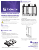
Installation Instructions

2
Unpacking the modules
Virtual Services Platform
8608 Module Installation
Acquire the following tools:
• Phillips #2 screwdriver
• Antistatic wrist strap
1
Prerequisites
This poster provides information and instructions to install the
I/O and control (IOC) modules and the switch fabric (SF)
modules vertically in the Extreme Virtual Services Platform 8608
chassis. The installation process is the same for both modules;
however, note that each module must be installed in a slot that
is designated for that module.
Electrostatic alert:
ESD can damage electronic
circuits. Do not touch electronic hardware unless you wear a
grounding wrist strap or other static-dissipating device.
Note: Observe Electrostatic discharge (ESD) precautions
when unpacking.
1. Verify package contents.The contents contains one
module and documentation. The documentation includes
how to locate software and Release Notes.
2. Remove the module from the box.
3. Remove the module from the anti-static bag. Handle the
module by the edges and avoid touching the components
or connector pins.
4. Visually inspect the connectors for damage. If you insert a
module with damaged connectors, you could damage the switch.
3
Installing the modules
Note: Ensure slot 1 or slot 2 contains an IOC module.
1.
Locate a free IOC or SF slot.
2 3 4 SF2 SF3 5 6 7 8SF11
Pwr
Status
RPS
Fan
USB
Console
Link/Act
In Use
Link/Act
In Use
2422
20
18
23211917
Link/Act In Use
Link/Act In Use
16
14
12
10
151311
9
Link/Act
In Use
Link/Act
In Use
8642
7531
6480 Via Del Oro
San Jose, CA 95119
Tel: +1 408-579-2800
Toll-free: +1 888-257-3000
WWW.EXTREMENETWORKS.COM
2. Remove the filler panel. Use a Phillips screwdriver to
loosen the top and bottom captive screws, and slide
the filler panel out.
3. Install the module. Rotate the top lever up and the
bottom lever down until the lever forms a 90° angle
with the front of the module.
4. Slide the module into the chassis, and apply light hand
pressure until the module connects with the backplane.
5. Rotate the top lever down and the bottom lever up
until the levers are flush with the module.
6. Secure the module in the chassis. Use a Phillips screw-
driver to tighten the top and bottom captive screws.
Do not overtighten.
Poster part nu
mber: 700513350 Rev 02
NN47229-302 02.01
12282-0817-18